Transient behavior of a control system, Electrical Engineering

Assignment Help:

Q. Transient behavior of a control system?

The transient portion of the time response of a stable control system is that part which goes to zero as time increases and becomes sufficiently large. The transient behavior of a control system is usually characterized by the use of a unit-step input. Typical performance criteria that are used to characterize the transient response to a unit-step input include overshoot, delay time, rise time, and settling time. Figure illustrates a typical unit-step response of a linear control system.

423_Transient behavior of a control system.png

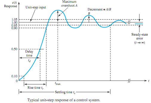
The following four quantities give a direct measure of the transient characteristics of the step response:

• Maximum (or peak) overshoot A is the largest deviation of the output over the step input during the transient state. It is used as a measure of the relative stability of the system. The percentage maximum overshoot is given by the ratio of maximum overshoot to final value, expressed in percent.

• Delay time td is defined as the time required for the step response to reach 90% of its final value.

• Rise time tr is defined as the time needed for the step response to rise from 10% to 90% of its final value.

• Settling time ts is the time required for the step response to decrease and stay within a specified percentage (usually 5%) of its final value.

While these quantities are relatively easy to measure once a step response is plotted, they cannot easily be determined analytically, except for simple cases.


Related Discussions:- Transient behavior of a control system

Explain position servo in a radar system, Q. Explain Position servo in a ra...

Q. Explain Position servo in a radar system? Figure depicts the essential elements of a position servo system. In a radar system, an electromagnetic pulse is radiated from an a

Switching, With neat diagrams explain the configuration of a step-by-step s...

With neat diagrams explain the configuration of a step-by-step switching system

Compute the transfer function from the input, In this project we will consi...

In this project we will consider the control of a synchronous generator supplying electricity to the grid. We will focus on the problem of frequency stability. The frequency at whi

Complete the timing diagram for counter, Q. When the J and K inputs of a JK...

Q. When the J and K inputs of a JKFF are tied to logic 1, this device is known as a divide-by-2 counter. Complete the timing diagram shown in Figure for this counter.

Show the dialling circuit, Q. Show the Dialling Circuit? Dialling circu...

Q. Show the Dialling Circuit? Dialling circuit enables subscriber to output signals representing digits, and this enables caller to enter destination telephone number. Dialling

Electrical drives, 'Electrical drives' is a general term that is commonly u...

'Electrical drives' is a general term that is commonly used to describe both DC and AC excited motors that provide continuous rotary motion, whilst 'electrical actuators' provide l

Calculate the iron loss, Q. The efficiency of a 400-kVA, single-phase, 60-H...

Q. The efficiency of a 400-kVA, single-phase, 60-Hz transformer is 98.77% when delivering full-load current at 0.8 power factor, and 99.13%with half rated current at unity power fa

Switching diode, how can I use switching diodes to achieve SPDT "relay" fun...

how can I use switching diodes to achieve SPDT "relay" function? 2 inputs 12vdc..for BI-Color LED.

Magnetism, What is mgnomotive force

What is mgnomotive force

Write Your Message!

Captcha
Free Assignment Quote

Assured A++ Grade

Get guaranteed satisfaction & time on delivery in every assignment order you paid with us! We ensure premium quality solution document along with free turntin report!

All rights reserved! Copyrights ©2019-2020 ExpertsMind IT Educational Pvt Ltd