Program for measures the wind direction-vane, Assembly Language

Assignment Help:

You are to create an assembly program for the MSP430 that correctly measures the wind direction, to a precision of 45° (N, NW, W, SW, S, SE, E, NE), using the MSP430's ADC.

Your program will output the direction using four LEDs, one each for N, S, E, and W. If the wind direction is out of the N, only the N LED will light. If the wind direction is out of the NW, both the N and W LEDs with be ON.

Note that the actual circuit interfacing to the wind vane will use the 3.6V supply on the

Launchpad board itself. This means that voltage readings provided in the table on the following page need to be appropriately scaled. As per the table, a 10kohm resistor will be used in the voltage divider.

As only one wind vane is available for use, test your code using a pot connected between ground and 3.6 V (the supply voltage for your board). The wind vane will be available in 310 for final check-out. Pots, LEDs, and resistors will be provided in 310.

Your program must use at least one subroutine. You are free to choose which functionality to place in the subroutine.

Extra Credit:

(1) Correctly measure all 16 directions possible by the vane. Develop some mechanism for visually displaying the added directions.

(2) Store the voltages corresponding to the specific directions as constants in a memory array (see example below). Have your code cycle through this array until a match is found.

ORG 0xD000

DC 0x1234, 0xABCD, ... ;replace w/ calculated voltages

Wind Vane

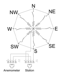
The wind vane is the most complicated of the three sensors. It has eight switches, each connected to a different resistor. The vane's magnet may close two switches at once, allowing up to 16 different positions to be indicated. An external resistor can be used to form a voltage divider, producing a voltage output that can be measured with an analog to digital converter, as shown below.

The switch and resistor arrangement is shown in the diagram to the right.

Resistance values for all 16 possible positions are given in the table.

Resistance values for positions between those shown in the diagram are the result of two adjacent resistors connected in parallel when the vane's magnet activates two switches simultaneously.

2042_anemometer.png


Related Discussions:- Program for measures the wind direction-vane

Daa-arithmetic instruction-microprocessor, DAA: Decimal Adjust Accumulator...

DAA: Decimal Adjust Accumulator:- This instruction is utilized to convert the result of the addition operation of 2 packed BCD numbers to a valid BCD number. The conclusion has to

8088 timing system diagram-Microprocessor, 8088  Timing System Diagram ...

8088  Timing System Diagram The 8088 address/data  bus is divided  in 3 parts (a) the lower 8 address/data  bits, (b) the middle 8 address bits, and (c) the upper 4 status/

Logical instruction-microprocessor, Logical Instruction : This type of...

Logical Instruction : This type of instructions is utilized for carrying out the bit by bit shift, basic logical operations or rotate. All of the condition code flags are affe

Project 1: Text Conversion, I need a text conversion program written in ass...

I need a text conversion program written in assembly language

Introduction to evaluation, This unit introduces the topic of evaluating in...

This unit introduces the topic of evaluating interactive products. It is a short unit as evaluation is discussed in more detail in Block 4. Its brevity should give you additional t

Interrupt table-how interrupt table processed-microprocessor, Interrupt Tab...

Interrupt Table Each interrupt level has a booked memory location, called an interrupt vector.  All these vectors (or pointers) are stored in the interrupt table. Table lies at

Name-offset-assemblers directive-microprocessor, NAME : Logical Name of...

NAME : Logical Name of a Module: The NAME directive which is used to assign a name to an assembly language program module. The modulecan now be mention to by its declared name.

Assignment, 1. Write an assembly program that adds the elements in the odd ...

1. Write an assembly program that adds the elements in the odd indices of the following array. Use LOOP. What is the final value in the register? array1 DWORD 10, 20, 30, 40, 50, 6

Write Your Message!

Captcha
Free Assignment Quote

Assured A++ Grade

Get guaranteed satisfaction & time on delivery in every assignment order you paid with us! We ensure premium quality solution document along with free turntin report!

All rights reserved! Copyrights ©2019-2020 ExpertsMind IT Educational Pvt Ltd