Inlet duct arrangement in aircraft engine, Other Engineering

Assignment Help:

Inlet duct arrangement in Aircraft Engine:

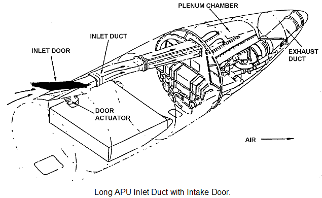
Wherever the APU is located, ducting will be required to bring air to the APU inlet. In figure 18.9. we can see that the inlet duct connecting the inlet door to the APU plenum chamber is divided into three parts. The plenum chamber has the APU inlet duct bolted to its structure, thus reducing a complicated duct joint arrangement. These ducts can be manufactured from various materials, but the most common are aluminium, titanium, steel or composite (fibre glass/carbon). Figure 18.8. shows a light alloy side mounted intake duct without an intake door.

When the duct length is short, steel or titanium ducts may be used. When ducts cover a large distance an unacceptable weight problem may result. Ducts of this length are therefore manufactured from light alloy or composite materials.
One of the main problems of APU's is the ingestion of foreign objects this can be eliminated by fitting wire mesh grills either in the ducting, or around the APU air inlet.

The length of the inlet ducts will depend upon the location of the APU and its distance from the inlet. Some APU inlets are fitted with a door, these are usually forward facing or top mounted inlets. The door will open before the APU starts and close after a time delay on APU shut down The duct may be short or fairly long as shown in the figure.
691_inlet duct arrangement.png 
Operation of the door opening and closing is achieved by using an electrical actuator, which receives its signal from a command from the flight deck APU switch.

138_inlet duct arrangement1.png

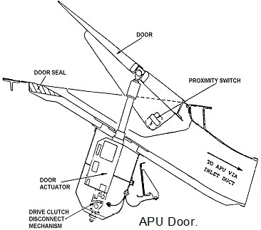
In the event of an electrical failure to an actuator, there is normally incorporated into the actuator a means of disengaging the clutch drive mechanism. This enables the actuator to be manually turned to open or close the inlet door.
A proximity switch ensures that the door is fully open before the APU start sequence is initiated.

APU inlet doors serve three functions:

• They seal off the inlet duct from harmful weather conditions and foreign objects when the APU is not in use.
• They open to allow air into the APU when the start sequence is initiated.
• They can be used to adjust the intake area when on ground in flight.

2203_inlet duct arrangement2.png

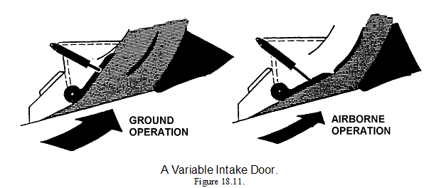
The variable intake door figure 18.11. is used to reduce the ram air entering the APU intake ducting. This could effect the APU fuel system if intake pressure is not taken into the calculation of engine fuel scheduling which is the case with most APU's .


Related Discussions:- Inlet duct arrangement in aircraft engine

Construction, notes on non tilting concrete drum mixers

notes on non tilting concrete drum mixers

Chains of inference, Chains of Inference Now we look at how to get an a...

Chains of Inference Now we look at how to get an agent to verify a given theorem using several search strategies. In previous lectures we have noted that, to specify a search p

Energy emission per capita, How do the numbers calculated in f. and g. comp...

How do the numbers calculated in f. and g. compare to the values in California and in the USA? The source of CO 2 emissions in Florida differ a lot from California. Transportat

Fire suppression in aircraft , Fire suppression Typical fixed systems i...

Fire suppression Typical fixed systems in the types of aircraft for which fixed fire extinguisher systems are specified, it is usual for the extinguishant to be stored in the c

Digital electronic.., design a 32:1 multiplexer using 16:1 multiplexer

design a 32:1 multiplexer using 16:1 multiplexer

Electronics, explain compensated semiconductors

explain compensated semiconductors

Normal spectrum, Q. What is a normal spectrum? Show that grating spectrum i...

Q. What is a normal spectrum? Show that grating spectrum is a normal spectrum. Ans. Normal spectrum and the dispersive power of grating is defined as the rate of change of a

Mine Drainage Task, The purpose of this project is to design a pipeline and...

The purpose of this project is to design a pipeline and pumping system to dewater a mine. The production level is 500m below surface. Ore is fed through crusher chambers to the tra

Nozzle guide vane inspection, Nozzle Guide Vane Inspection: Inspection ...

Nozzle Guide Vane Inspection: Inspection of the NGVs is possible using a strong light source and mirror, it is more probable however that a boroscope inspection will be require

Write Your Message!

Captcha
Free Assignment Quote

Assured A++ Grade

Get guaranteed satisfaction & time on delivery in every assignment order you paid with us! We ensure premium quality solution document along with free turntin report!

All rights reserved! Copyrights ©2019-2020 ExpertsMind IT Educational Pvt Ltd