Explain solid-state control of dc motors, Electrical Engineering

Assignment Help:

Q. Explain Solid-State Control of DC Motors?

Dc motors, which are easily controllable, have historically dominated the adjustable-speed drive field. The torque-speed characteristics of a dc motor can be controlled by adjusting the armature voltage or the field current, or by inserting resistance into the armature circuit . Solid-state motor controls are designed to use each of these modes. The control resistors, in which much energy is wasted, are being eliminated through the development of power semiconductor devices and the evolution of flexible and efficient converters.

878_Explain Solid-State Control of DC Motors.png

Thus, the inherently good controllability of a dc machine has been significantly increased in recent years by rectifier control, chopper control, and closed-loop control of dc motors. When a dc source of suitable and constant voltage is already available, designers can employ dc-to-dc converters or choppers. When only an ac source is available, phase-controlled rectifiers are used. When the steady-state accuracy requirement cannot be satisfied in an open loop configuration, the drive is operated as a closed-loop system. Closed-loop rectifier drives are more widely used than chopper drives. Only rectifier control of dc motors is considered here.

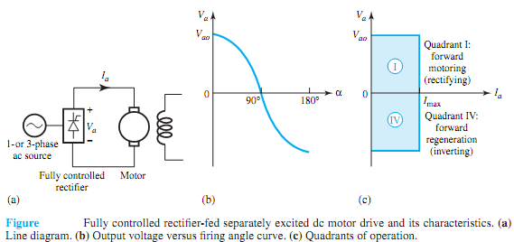
Controlled rectifier circuits are classified as fully controlled and half-controlled rectifiers, which are fed fromeither one-phase or three-phase supply. Figure shows a fully controlled, rectifier-fed, separately excited dc motor drive and its characteristics. A transformer might be required if the motor voltage rating is not compatible with the ac source voltage. To reduce ripple in themotor current, a filter inductor can be connected in series between the rectifier and themotor armature. The field can be supplied from the same ac source supplying the armature, through a transformer and a diode bridge or a controlled rectifier. While single-phase controlled rectifiers are used up to a rating of 10 kW, and in special cases even up to 50 kW, three-phase controlled rectifiers are used for higher ratings.


Related Discussions:- Explain solid-state control of dc motors

Activities to preparing long-term plans, Activities to Preparing Long-term ...

Activities to Preparing Long-term Plans 1. Data collection regarding existing loads, forecast of expected loads, operating conditions, and etc. from Grid substation up to cons

Ultrasonic Sensor Help for Seventh Grader, What are ultrasonic sensors made...

What are ultrasonic sensors made of? What is a good online source to find information on a basic level about ultrasonic sensors?

Psuedo code, Ask questiIn a right triangle, the square of the length of one...

Ask questiIn a right triangle, the square of the length of one side is equal to the sum of the squares of the lengths of the other two sides. Stephanie has the integer lengths of t

Show bandwidth of the system, A communication system for a voice-band (3 kH...

A communication system for a voice-band (3 kHz) channel is designed for a received SNR E b /N 0 at the detector of 30 dB when the transmitter power is Ps =-3 dBW. Find the value o

What are shift registers, What are shift registers? Design a 8 bit shift re...

What are shift registers? Design a 8 bit shift register with features like PISO, SISO, SIPO and PIPO.

Explain different routing plan adopted in a network, Q. Explain different R...

Q. Explain different Routing plan adopted in a Telephone network.  Ans: Hierarchical networks are capable of handling heavy traffic where required, and at the same time us

Draw a labeled block diagram of the encoder, Question: (a) The convers...

Question: (a) The conversion of a time varying analog audio signal into digital form is carried out using an electronic circuit known as a (signal) encoder. Draw a labeled bl

Explain the working principle of an opto coupler, Q. Explain the working pr...

Q. Explain the working principle of an opto coupler? When it is necessary to block the voltage between one electronic circuit and another, and transfer the signal at the same t

Show quantization error, Quantization Error Sampling followed by quanti...

Quantization Error Sampling followed by quantization is equivalent to quantization followed by sampling. Figure illustrates a message signal f (t) and its quantized version den

Write Your Message!

Captcha
Free Assignment Quote

Assured A++ Grade

Get guaranteed satisfaction & time on delivery in every assignment order you paid with us! We ensure premium quality solution document along with free turntin report!

All rights reserved! Copyrights ©2019-2020 ExpertsMind IT Educational Pvt Ltd