Explain hall effect with hall mobility and hall angle, Electrical Engineering

Assignment Help:

Explain Hall effect.

Consider a slab of material wherein there is a current density J resulting by an applied electric field Ex in the x- direction. The electrons will drift along with an average velocity V‾x in the x direction; while a magnetic field of flux density Bz (wb/m2) is superposed upon the applied electric field in the Z direction the electrons will experience a Lorentz force perpendicular to V‾x and to Bz; the magnitude of this force will be specified by Bz (µx)e.
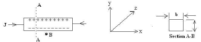
1737_hall effect1.png

Thus the electrons are driven towards one face in the sample resulting in an excess of electrons near one face and a deficiency of electrons near the other face. These charges will in turn create a counteracting electric field Ey in the y-direction. Ey would build up, till this is of sufficient magnitude to compensate the lorentz force exerted on the electrons because of the magnetic field we may hence write e Ey =Bz e( V‾x ). In steady state, a Hall voltage, VH, is thereby put in the y-direction specified by

VH = Ey .a =Bz (V‾x), a

The current density in the sample is specified with:

Jx = N. e (V‾x)

Here N=number of conduction electrons/m³

The current density can be computed from the total current and the cross section (a x b) of the sample.

Therefore,

Jx = I/a x b = N. e (V‾x)

I = N. e (V‾x) a x b   ....................................(1)

VH = BZ (V‾x) . a    ......................................(2)

Eliminating (V‾x) from equating (1) and (2) we get:

VH = I/(N.e.b)

= (1/N.e) ((BZ.I)/b)

The ratio + (1/N.e) = Ey/(JX.BZ) should be constant.

Another variable that is frequently used to explain the Hall Effect is the ratio of the currents JY to JX.

This is termed as the Hall angle and is denoted with θ θ = JY / JX = σ EY / JX

= σ RH BZ

= µ H BX

Here µ H is termed as the Hall mobility. The hall angle is equal to the average no. of radians traversed through a particle between collisions.


Related Discussions:- Explain hall effect with hall mobility and hall angle

Motor, operation of induction motor

operation of induction motor

Derive the transfer function, A data hold is to be constructed that reconst...

A data hold is to be constructed that reconstructs the sampled signal by the straight-line approximation shown in Figure. Note that this device is a polygonal data hold with a dela

Bode plot, Hai.. i have been given a open loop transfer function to draw a...

Hai.. i have been given a open loop transfer function to draw a bode plot with a particular K value and they asked me to find the value of K for which the phase margin becomes 45d

Sketch the inductor voltage and stored energy, (a) Consider a 5-µH inductor...

(a) Consider a 5-µH inductor to which a current source i(t) is attached, as shown in Figure (b). Sketch the inductor voltage and stored energy as a function of time. (b) Let a v

Analog & Digital Filtering, 1) Assume that we are given the continuous-time...

1) Assume that we are given the continuous-time signal xa (t) = xa1 (t) + xa2 (t) + xa3 (t), where, xa1 (t) = 2 + cos3 (2pf1 t + p 3 ) + 2 cos(2pf2 t), xa2 (t) = 2 cos(2pf3 t)

Branch current method, if a resistor present in the middle of two branches ...

if a resistor present in the middle of two branches in such a way that their polarities coincide then how do we choose the polarity of that resistor

.#title.Simulation on Half wave rectifier using PSpice, How to plot output ...

How to plot output power Vs load resistor graph using PSpice softwaer for half wave rectifier circuit

Dual trace and dual beam cro, what is difference between dual trace and dua...

what is difference between dual trace and dual beam cro?

Write Your Message!

Captcha
Free Assignment Quote

Assured A++ Grade

Get guaranteed satisfaction & time on delivery in every assignment order you paid with us! We ensure premium quality solution document along with free turntin report!

All rights reserved! Copyrights ©2019-2020 ExpertsMind IT Educational Pvt Ltd