Reference no: EM132843762
CTEC3606 Multi-Service Networks - De Montfort University
Assignment - MSN2 Deferral & Resit Coursework
Learning outcome 1: IPv4 Variable Length Subnet Mask (VLSM)
Learning outcome 2: StaticRouting
Learning outcome 3: Distance Vector Routing Protocols(RIP)
Learning outcome 4: Link State RoutingProtocols
Learning outcome 5: MultiareaOSPF
Learning outcome 6: Network Address Translation(NAT)
Learning outcome 7: Voice over IP(VoIP)
Part 1: IPv4 Addressing
A. Subnet 200.25.11.0/24 to address the network topology depicted in Figure 1. Use the most efficient addressing possible. You have to present your stepwise solution with justification. Showing just the final subnets assignment will not beaccepted.
B. You have decided to add a new serial link between Bldg1 and NY routers. What do you need to do to address the newly created network between the tworouters?
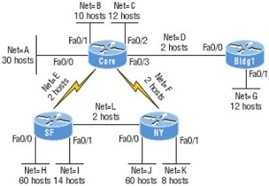
Figure 1
Part 2: Dijkstra's Shortest Path First Algorithm
Figure 2 shows a network with nodes ‘a' to ‘f' (these are shown circled) with the indicated link costs, use Dijkstra's algorithm to compute the least cost path from node ‘a' to all network nodes. Show how the algorithm works by computing a Link-state (LS) table. Then show the least cost path and the forwarding table for source node ‘a'. You have to present a stepwise solution supplemented with proper justification. Showing the final results only will not be accepted.
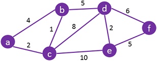
Figure 2
Part 3: Network Configuration
Consider the following network topology depicted in Figure 3 and implemented in CW.pktfile. As a network engineer, you have been requested to accomplish tasks {A, B, C, D, E, F, G, H, and I} listed below. You need to configure the network in the supplemented file ‘CW.pkt' according to these tasks while providing a detailed justification for each one in your report. You are not supposed to change the configuration of any end-device, i.e., a workstation, a server, or an IP-Phone unless you
are clearly requested to do so.
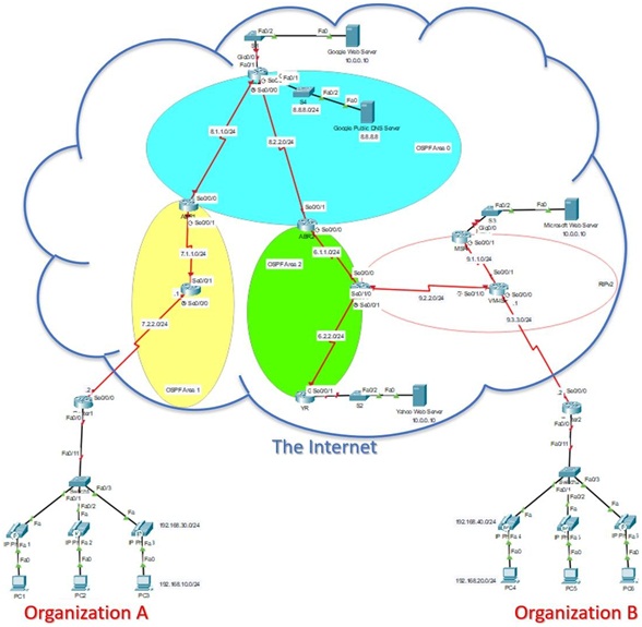
Figure 3
[A clearer figure is provided in the supplemented file ‘CW.pkt']
A. Following the network labels, configure all of the routers' serial interfaces with DCE and DTE ends set to .1 and .2 IP addresses respectively. Clock rates have to be configured according to Table 1. Note: In your report, including justification for a single serial link configuration will besufficient.
Table 1
|
Area
|
Clock Rate
|
|
OSPF Backbone Area
|
2000000
|
|
OSPF Area 1, Area 2 and RIPv2 Area
|
128000
|
|
Links to organizations A and B
|
64000
|
B. All web servers on the Internet is approachable only via their public IP addresses as registered on Google Public DNS Server (already provided in file ‘CW.pkt'). Their private IP addresses are not routable and should not be disclosed to public. Configure their gateways to enforce this rule. Hint:useNAT.
C. Configure RIPv2 in thered-circledarea.
D. Configure Multiarea OSPF {area 0, area 1, and area 2} giving proper routesummarization,correctcost information, and router-id(s)ifneeded.
E. Redistribute RIPv2 updates into OSPF andviceversa.
F. Configure all of the devices in Organization A. Router 1 should act as a DHCP server for all of the workstations and IP Phones. They should all get private, unrouteable IP addresses as per the depicted network labels. PCs should be able to access the Internet via BT-ISP. IP-Phones should be allocated the following numbers depicted in Table2:
Table 2
|
Phone
|
Number
|
|
IP Phone1
|
1001
|
|
IP Phone2
|
1002
|
|
IP Phone3
|
1003
|
Repeat the same for Organization B with IP-Phones allocated numbers shown in Table 3.
Note: Justification is not required for Organisation B.
Table 3
|
Phone
|
Number
|
|
IP Phone4
|
2001
|
|
IP Phone5
|
2002
|
|
IP Phone6
|
2003
|
G. Enable telephone communication between Organization A and B. Hint: configure adial-peer.
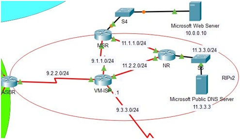
H. Microsoft has decided to offer its own public DNS service. For that, the topology is updated according to Figure 4. Update the topology and the configuration of ‘CW.pkt' file so that the newly created Microsoft Public DNS Server is reachable using its public IP address 11.3.3.3. Do you notice any issues in the network? If yes, discuss how to solve them.
I. Google has decided to create a server farm in order to serve more customers. Consider the update depicted in Figure 5, how would you use NAT to implement load-balancing across the serverfarm?
Note: The required configuration is not currently supported by Cisco Packet Tracer, you just need to figure it out manually in your report with proper justification just like other tasks.
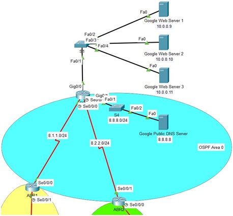
Figure 5
Attachment:- Multi-Service Networks.rar