What are the performance measures of oscillator circuits, Electrical Engineering

Assignment Help:

Q. What are the performance measures of oscillator circuits?

1. Stability: This is determined by the passive components. R, C and L determine frequency of oscillations. If R changes with T, f changes so stability is affected. Capacitors should be of high quality low leakage. So silver mica and ceramic capacitors are widely used.

2. Amplitude stability: to get large output, amplification is to be done.

3. Output power: class A, B and C operations can be done. Class C gives largest output but harmonics are more.

4. Harmonics: Undesirable frequency components are harmonics. An elementary sinusoidal oscillator circuit is shown in figure.

2393_What are the performance measures of oscillator circuits.png

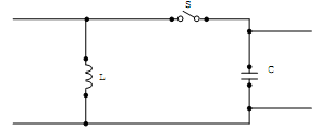
L and C are reactive elements. They can store energy. The capacitor stores energy whenever there is voltage across its plates. Inductor stores energy in its magnetic field whenever current flows. Both C and L are lossless, ideal devices. So quality factor is infinity. Energy is introduced into the circuit by charging capacitor to 'V' volts. If switch is open, C cannot discharge because there is no path for discharge current to flow.

Voltage across C is V volts. When switch is closed, current flows. So the charge across capacitor C decreases and voltage across C decreases. so as the energy stored in capacitor decreases, the energy stored in inductor L increases, because current is flowing through L. thus total energy in the circuit remains the same as before. When V across C becomes 0, current through the inductor is maximum and the current starts charging C in the opposite direction. So V across C becomes negative. Thus we get sinusoidal oscillations from LC circuit.


Related Discussions:- What are the performance measures of oscillator circuits

What is the procedure of binary division, Q. What is the procedure of Binar...

Q. What is the procedure of Binary Division? The Binary division is the repeated process of subtraction, just as in decimal division. Signed Numbers Representation If w

Fixed and adaptive - optimal filtering, Optimal Filtering A syste...

Optimal Filtering A system identi?cation structure is shown in Figure 1. The discrete-time signal [ ] forms the input to an unknown system represented by a moving average

Minimized circuit not -or and gate, 1.  Given S(D1) = !Q1 X + !Q1 Q0 + Q1 !...

1.  Given S(D1) = !Q1 X + !Q1 Q0 + Q1 !Q0 !X                                                        and       S(D0) = !Q1 !Q0 !X + Q0 X + Q1 !Q0 !X       A.  DRAW A MINIMI

Explain practical digital to analog converters, Explain Practical Digital t...

Explain Practical Digital to Analog Converters? In several DSP applications, we must reconstruct an analog signal after the digital processing stage. This is completed using a

Explain classification of energy band materials, With the help of energy ba...

With the help of energy bands explain how conduction takes place in conductors, semiconductors and insulators. On the basis of energy band materials are categorized as insulato

Define the binary counting - counters, Define the Binary Counting - Counter...

Define the Binary Counting - Counters? The Binary counter is capable to be constructed from J-K flip-flops by taking the output of one cell to the clock input of the next The J

Express the instantaneous power, Q. On a per-phase basis, let v = √2 V cos ...

Q. On a per-phase basis, let v = √2 V cos ωt and i = √2 I cos (ωt - θ). (a) Express the instantaneous power s(t) in terms of real power P and reactive power Q. (b) Now consid

Automatic irrigation system on running solar power b, how to upload the pro...

how to upload the program on proteus soft ware by using personal computer?

Npn bjt with forward-biased, NPN BJT with forward-biased: An NPN trans...

NPN BJT with forward-biased: An NPN transistor can be referred as two diodes along with a shared anode. In common operation, the base-emitter junction is forward biased and th

V-i characteristics - power semiconductor devices , V-I Characteristics ...

V-I Characteristics  In the  normal  mode of  operation of an IGBT  a positive  voltage is applied to the collector relative to emitter. When  the gate is at zero potential wi

Write Your Message!

Captcha
Free Assignment Quote

Assured A++ Grade

Get guaranteed satisfaction & time on delivery in every assignment order you paid with us! We ensure premium quality solution document along with free turntin report!

All rights reserved! Copyrights ©2019-2020 ExpertsMind IT Educational Pvt Ltd