Aims
- Exploring the analog output capabilities of the PIC trainer
- Write PIC assembly code to implement a simple multi-function signal generator Equipment
- PIC Trainer and PICkit3 in-circuit debugger
- MPLAB Integrated Development
Environment software
Background documents (available on FLO)
- MPASM Assembler Users Guide
- PIC18F452 Instruction Set Summary
- MAX5102 Digital to Analog Converter Data Sheet
- HM407-2 Oscilloscope User Manual
Checkpoint 1: Sawtooth Waves
1. Set DIP switch 3 on the PIC Trainer to enable the DAC, and DIP switch 4 to enable the AN0 and AN1 potentiometers.
2. Create a new MPASM project named prac4, making sure that the processor and toolsuite are correct for the PIC Trainer, the configuration bits are set to the appropriate values, and the correct debugger selected. Create a new project source file named siggen.asm
3. Write an initialisation subroutine, init, to configure the PIC processor so that bits 4 and 5 of port A and all bits of port D are outputs.
4. Write a subroutine, DAC_A that outputs the value in WREG to output A of the DAC. The subroutine should place the output value on PORTD (connected to pins D0 to D7 of the DAC chip), select DAC output A by clearing RA5 (DAC pin A0), then latch the value into the DAC by pulsing RA4 low for 1 instruction cycle (DAC pin WR).
5. Write a main program to generate a sawtooth wave. Your program should call init, then enter a loop that loads a counter variable into WREG, calls DAC_A to output the value, and then increments the counter. The successive values of the counter will generate a steadily increasing voltage on the DAC output. When the counter reaches h'FF' and overflows back to zero, the output voltage will fall to zero to begin a new cycle of the output wave.
6. Connect DAC output A to Input CH I on the HM407 CRO using a BNC cable. Turn on the CRO, and adjust the controls to display the output waveform so that a single cycle occupies most of the screen. Make sure the input coupling for CH I (control 32 on the control panel diagram) is set to DC, then use the Y-POS I control (13) and X-POS control (18) to position the waveform so you can measure the amplitude and period of the waveform as accurately as possible. You might find it convenient to use the cursor controls (43) to adjust the on-screen cursor to measure the waveform and display the measurements directly on the CRO screen.
7. Compare the measured values for amplitude and period with the values you would expect to see. To predict the waveform period, you will need to carefully count the number of cycles in your program loop, including the instructions involved in the subroutine call and return. Don't forget that some instructions take two instruction cycles to execute. The PIC trainer uses a 10 MHz clock, and in HS oscillator mode each instruction cycle takes 4 clock cycles, so an instruction cycle is 0.4 µs long.
Checkpoint 2: Other Wave Shapes
8. Modify your program so that it outputs a square wave instead of a sawtooth wave. One way to make the change is to write a subroutine that returns either h'00' or h'FF', depending on whether it was called with WREG less than h'80' or not. Then you can call the subroutine to map the counter into the appropriate output value before calling DAC_A. An easy way to test whether a value is less than h'80' is to examine the most significant bit.
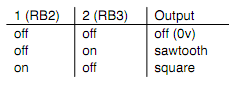
9. Modify the program so that you can switch between sawtooth and square wave output using the DIP switches next to the red and green pushbuttons (which are connected to various bits of port B), as shown in the following table. Note that the switches are active low, so the value you read on PORTB will be 1 when a switch is off and 0 when it is on.
10. Extend the program so that it will generate sine wave output if switches 1 and 2 are both on. To generate the sine wave, write a subroutine that uses a lookup table to map the value in WREG into a suitably scaled and shifted approximation of the sine function. To compute the values for the entries in the lookup table, use a spreadsheet to generate text output suitable for pasting into the source code. The appropriate values for the lookup table are given by the
Formula
f = 128(1 + sin (2π ·w/256 ))
11. Because the table will need 256 entries, the simple "computed jump" approach will not work. Instead, you'll need to use the PIC table lookup instructions to read the table values. Load the address of the beginning of the table into the TBLPTR registers, add the table offset (the value in WREG), then use the tblrd* instruction to load the value into TABLAT. Since the table address is a 22-bit value and you can only add 8 bits at a time, you'll need to allow for a possible carry from the low byte into the high byte and from the high byte into the upper byte.
Checkpoint 3: Controlling the Frequency
12. Extend your program so that it reads the value of the AN0 potentiometer and uses the value to control the frequency of the output waveform. Your program should define a subroutine to read the current value from the pot and return it in WREG. You will also need to modify the init subroutine to set up the PIC for analog input. The ADC should be configured with 5 analog channels and 3 digital I/O channels (PCFG mode b'0010'), a conversion clock of FOSC/16, and left-justified result format. You'll need to consult the PIC data sheet to determine the appropriate values for ADCON0 and ANCON1.
13. The analog input subroutine will need to perform the following steps:
- Adjust any ADC parameters if necessary.
- Wait for the required acquisition time; for the PIC trainer, it is sufficient to delay for 20µs, which corresponds to 50 instruction cycles.
- Set the GO bit in ADCON0 to start conversion.
- Loop until GO/_DONE is cleared, indicating the conversion is complete.
- Read the high 8 bits of the result from ADRESH.
14. Modify your main loop to call your ADC subroutine, then use the value returned to control the number of cycles in the loop and therefore the output waveform period. For example, you could use the ADC value to initialise a loop counter in an extra delay loop. The characteristics of the extra delay should be chosen so that the range over which the period can be varied (as AN0 varies from 0V to 5V) is around 10:1
15. Display the output waveform on the CRO, and hence accurately measure its minimum and maximum period and the corresponding frequencies.
Checkpoint 4: Controlling the Amplitude
16. Extend the program so that it uses the value of the AN1 potentiometer to control the amplitude of the waveform. When the pot is rotated to the 0V position, the amplitude should be zero, and when it is rotated to the 5V position the amplitude should be 5V peak-to-peak.
17. Modify your code so that as the amplitude is varied, the "DC value" of the waveform remains constant at 2.5V (half of the VDD value). For example, if the output is a square wave of 2V pp amplitude, the actual output voltage level should swing from 1.5V to 3.5V.
To Explore Further
18. (Straightforward) Add other waveforms to the signal generator. For example, you could add a triangular wave, a "staircase", or a "reverse sawtooth".
19. (Moderate) Extend the program so that DAC output B outputs a sine wave (no matter what mode the signal generator is in) that is synchronised with the output A waveform.
20. (Difficult) Provide a way to vary the "DC offset" of the signal, for example by using the AN1 potentiometer while one of the pushbuttons is held down. Make sure that something "reasonable" happens when the signal is clipped.
21. (Difficult) Connect up several PIC trainers to build more complex signal generators. For example, you could build a sweep generator by using one trainer to generate a sawtooth output that is then used to control the frequency of another trainer. Or you could create a modulated signal by using the output from one trainer to control the amplitude of another.
22. (Challenging) Take advantage of the symmetry of a sine wave to reduce the size of the sine-wave lookup table. You only need to store values for the first quarter of the period; the remaining values can be generated by shifting and reflecting.