What is autotransformers, Electrical Engineering

Assignment Help:

Q. What is Autotransformers?

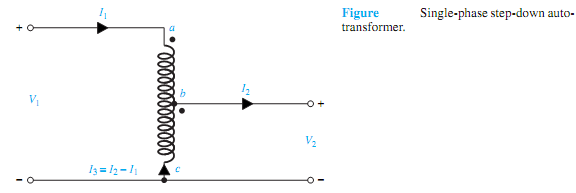
In contrast to a two-winding transformer, the autotransformer is a single-winding transformer having a tap brought out at an intermediate point. Thus, as shown in Figure a-c is the single N1-turn winding wound on a laminated core, and b is the intermediate point where the tap is brought out such that b-c has N2 turns. The autotransformer may generally be used as either a step-up or a step-down operation. Considering the step-down arrangement, as shown in Figure, let the primary applied voltage be V1, resulting in amagnetizing current and a core flux φm. Voltage drops in the windings, exciting current, and small phase-angular differences are usually neglected for the analysis. Then it follows that

2036_Autotransformers.png

in which a> 1 for step-down, a< 1 for step-up transformers.

The input apparent power is S1 = V1I1, while the output apparent power is given by S2 = V2I2. The apparent power transformed by electromagnetic induction (or transformer action) is Sind = V2I3 = (V1-V2)I2. The output transferred by electrical conduction (because of the direct electrical connection between primary and secondarywindings) is given by Scond = V2I2-V2I3 = V2I1.

1024_Autotransformers1.png

For the same output the autotransformer is smaller in size, weighing much less than a two- winding transformer, and has higher efficiency. An important disadvantage of the autotransformer is the direct copper connection (i.e., no electrical isolation) between the high- and low-voltage sides. A type of autotransformer commonly found in laboratories is the variable-ratio autotransformer, in which the tapped point b is movable. It is known as the variac (variable ac). Although here, for the sake of simplicity, we have considered only the single-phase autotransformer, three-phase autotransformers, which are available in practice, can be modeled on a per-phase basis and also analyzed just as the single-phase case.


Related Discussions:- What is autotransformers

TTL NAND gate, Q. Explain working of TTL NAND gate? The TTL logic famil...

Q. Explain working of TTL NAND gate? The TTL logic family uses only transistors instead of a combination of transistors and diodes. TTL has the same high and low ranges as DTL.

inverters- recifiers and inverters, Inverters Inverter is a device w...

Inverters Inverter is a device which  converts dc power into ac  power at desired output voltage and frequency. Inverters are used in  uninterruptible power  supply  hvdc  tra

Digital control system, Please suggest recent application of DCS WHICH I CA...

Please suggest recent application of DCS WHICH I CAN USE AS A TOPIC OF MY Ph.D.

What is an usart, What is an USART? USART stands for universal synchron...

What is an USART? USART stands for universal synchronous/Asynchronous Receiver/ Transmitter. It is a programmable communication interface that can communicate by using either s

Why negative feedback is employed in wein bridge oscillator, Q. Why negativ...

Q. Why negative feedback is employed in Wein Bridge Oscillator. Also explain the working of oscillator? The Wein Bridge Oscillator consists of two stages of the RC coupled ampl

Compute the signal-to-noise ratio, Q. (a) An ampli?er with F 0 = 3 or 4.77...

Q. (a) An ampli?er with F 0 = 3 or 4.77 dB, f 0 = 4 GHz, and BN = 14 MHz is used with an antenna forwhich T a =200K. The connecting path loss is 1.45, or 1.61 dB at a physical t

Design a water supply scheme for a station, Q. Design a water supply scheme...

Q. Design a water supply scheme for a station, adopting the following data - a) Source of water - River flow at a distance of 1 km. b) Requirement of water - 1 lack gallons p

Evaluate gm and pm for the asymptotic bode plot, Q. The loop gain of an ele...

Q. The loop gain of an elementary feedback control system(see Figure) is given by G(s)·H(s), which is 10/(1+s/2)(1+s/6)(1+s/50). Sketch the asymptotic Bode plot of the loop-gain fu

Find the largest current out, Q. Consider a BJT switch connected to the nex...

Q. Consider a BJT switch connected to the next stage, as shown in Figure, in which iout is likely to be negative when v out is high. Assume V CC = 5 V, R C = 1k, and the high r

Write Your Message!

Captcha
Free Assignment Quote

Assured A++ Grade

Get guaranteed satisfaction & time on delivery in every assignment order you paid with us! We ensure premium quality solution document along with free turntin report!

All rights reserved! Copyrights ©2019-2020 ExpertsMind IT Educational Pvt Ltd