What do you mean by magnetic circuits, Electrical Engineering

Assignment Help:

Q. What do you mean by Magnetic circuits?

A magnetic circuit provides a path for magnetic flux, just as an electric circuit provides a path for electric current.Magnetic circuits are integral parts of transformers, electric machines, and many other common devices such as doorbells. Analogous to voltage (electric potential difference) in the electric circuit, in a magnetic circuit we have the magnetomotive force (mmf), or the magnetic potential difference which produces a magnetic field, and which has units of amperes or ampere turns. The two sources of mmf in magnetic circuits are the electric current and the permanent magnet (which stores energy and is capable of maintaining a magnetic field with no expenditure of power). The current source is commonly a coil of N turns, carrying a current I known as the exciting current; the mmf is then said to be NI At.

184_What do you mean by Magnetic circuits.png

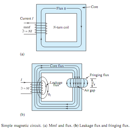
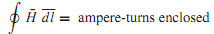
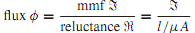
Figure (a) shows, schematically, a simple magnetic circuit with an mmf ℑ (= NI) and magnetic flux φ. Note that the right-hand rule gives the direction of flux for the chosen direction of current. The concept of a magnetic circuit is useful in estimating the mmf (excitation ampere-turns) needed for simple electromagnetic structures, or in finding approximate flux and flux densities produced by coils wound on ferromagnetic cores.Magnetic circuit analysis follows the procedures that are used for simple dc electric circuit analysis. Calculations of excitation are usually based on Ampere's law, given by

999_What do you mean by Magnetic circuits1.png

where H(| ¯H|= B/µ) is the magnetic field intensity along the path of the flux. If the magnetic field strength is approximately constant (H = HC) along the closed flux path, and lC is the average (mean) length of the magnetic path in the core, Equation can be simplified as

2324_What do you mean by Magnetic circuits2.png

Analogous to Ohm's law for dc electric circuits, we have this relation for magnetic circuits,

2040_What do you mean by Magnetic circuits3.png

where µ is the permeability, A is the cross-sectional area perpendicular to the direction of l, and l stands for the corresponding portion of the length of the magnetic circuit along the flux path. Based on the analogy betweenmagnetic circuits and dc resistive circuits, Table summarizes the corresponding quantities. Further, the laws of resistances in series and parallel also hold for reluctances.


Related Discussions:- What do you mean by magnetic circuits

Calculate the current flow using thevenin''s theorem, Calculate the curren...

Calculate the current flow in 30Ω resistor for the circuit in figure using Thevenin's Theorem.

Explain the operation of the counter, Q. Figure shows the mod-8 counter whi...

Q. Figure shows the mod-8 counter which counts from 010 to 710 before resetting. Explain the operation of the counter and sketch the timing diagram.

Electronics, Let me know if you can help during the test

Let me know if you can help during the test

\, Refer to Figure 100. Assume MKS units. Given: R1= 4, R2=14, R3= 9, I4...

Refer to Figure 100. Assume MKS units. Given: R1= 4, R2=14, R3= 9, I4= 8, I5= 7. Determine: Ieq, Req, and V3.

Determine the minimum needed frequency range, The operating frequency range...

The operating frequency range of a superheterodyne FMreceiver is 88-108MHz. The IF and LO frequencies are so chosen that f IF LO .Ifthe image frequency f  c must fall outside of

find power flow solution for the system, For the 3 bus system shown below ...

For the 3 bus system shown below all values are given in pu on a 100MVA base (a) Use Matlab functions lfgauss and lfnewton to find power flow solution for the system, accurate

Calculate total internal resistance, One battery having of four cells, conn...

One battery having of four cells, connected in series. Emf of each cell is 1.45V and internal resistance of 0.04Ω. if a load resistance of 5Ω is connected to the battery, draw the

Simple zener voltage regulator, Consider a simple zener voltage regulator w...

Consider a simple zener voltage regulator with the circuit diagram shown in Figure (a). (a) For a small reverse resistance R Z S and V S - R S i out > V Z , show that v ou

History - field-effect transistor, History - Field-Effect Transistor: ...

History - Field-Effect Transistor: The principle of field-effect transistors was very first patented by Julius Edgar Lilienfeld in the year 1925 and by Oskar Heil in the year

Factors which affect the inductance of an inductor, Factors which affect th...

Factors which affect the inductance of an inductor include:  i)  The number of turns of wire (N) - more turns the higher the inductance ii)  The cross-sectional area of the

Write Your Message!

Captcha
Free Assignment Quote

Assured A++ Grade

Get guaranteed satisfaction & time on delivery in every assignment order you paid with us! We ensure premium quality solution document along with free turntin report!

All rights reserved! Copyrights ©2019-2020 ExpertsMind IT Educational Pvt Ltd