Note transducers convert a physical quantity from one form to another. The case below illustrates a typical moving coil meter that converts a current into a mechanical angular displacement
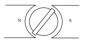
The coil is wound on an aluminium frame (aluminium is non-magnetic, hence µ~µ0 )supported on two pivots top and bottom. The frame rotates over a soft iron core (with a v.high µ), that is fixed. It does not rotate with the coil because the coil and frame should have minimum inertia for a rapid response to transient currents. Magnets either side, have shaped pole pieces to ensure that the coil experiences the field in a constant air gap regardless of the angle of the coil on the core. To ensure maximum field strength for a given permanent magnet strength, the two air gaps (one either side of the coil) are the only air gaps in the magnetic circuit. If a current flows in the coil, the coil experiences a torque due to the Lorenz force between the current carrying vertical edges of the coil and the magnetic field. This torque causes a deflection of the coil against a restraining spring so the final equilibrium position of the coil is a measure of the torque being experienced by the coil, which in turn is proportional to the current flowing in it.
A needle attached to the moving coil rotates along a scale calibrated to read current, voltage etc. In the case of a voltmeter, the coil has a large number of turns so that a reasonable torque is produced with very little current - i.e. the meter has a high resistance and draws very little current. In contrast, a current meter will have relatively few turns of large diameter, so the torque is produced by a relatively large current. It represents very little resistance and drops very little voltage. Because of the shaped pole pieces, the field is radial and constant across the air gap. Hence the force experienced by each vertical edge of the coil is:
F=B.i.L.N
where B = flux density
i = current flowing in the coil
l = length of the coil edge
N = number of turns on the coil.
If the coil is d metres wide, the total torque produced on the coil is:
T=2.B.i.L/N.d/2=B.i.N.A
If the spring has a spring constant c Newton.metres/radian (hence the spring constant is the torque required to produce an angular movement of one radian), then the current in the coil in equilibrium is :
i=c. O/B.A.N
Thus i and θ have a linear relationship and the sensitivity of an ammeter is expressed as:
O/i=B.A.N/c
For a voltmeter the sensitivity is expressed in terms of θ and the applied voltage. This may be related to the coil resistance R by
v= i.R , so
O/v=B.A.N/c.R
Moving coil meters can (but not always) have high sensitivity, uniform scale and low power consumption. However, to meet all these requirements they will be expensive, especially if high sensitivity is required, (N high, c low) and will not be very robust. They are used for DC only. (AC meters of this construction are readily available, but these convert AC into DC first, using a rectifier).