Simply supported beam - shear force diagram, Mechanical Engineering

Assignment Help:

Simply supported beam - Shear Force diagram:

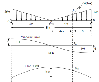
A simply supported beam of length 8 m is subjected to a consistently varying load from zero at centre to 3 t/m at both of ends. Draw the BMD and SFD.

Solution

Taking moment around A,

R B  × 8 - (½) × 4 × 3 (4 × (2/3) × 4 ) - 1 × 4 × 3( (1/3) × 4 )  = 0

RB = 6 t

R   = ( (½) × 4 × 3) × 2 - R B     = 12 - 6 = 60

On the other hand, since the load is symmetrical, the reaction at the support shall be equal to half of the entire downward load.

RA  = RB  = 6 t

316_Simply supported beam - Shear Force diagram.png

Figure

Shear Force

SF at A,          FA  = +6t          

SF at C,                    FA   =+ 6 - (½) × 4 × 3 = 0

SF at B,                      FB   = 0 - (1 /2)× 4 × 3 = - 6 t  = Reaction at B.

 To determine the form of SFD, let a section XX at a distance 'x' from the end B.

F x  =- 6 + (½) × x × ( 3 + (3 /4)(4 - x) )

   =- 6 + (½) × x × (12 + 3 (4 - x) /4)

F x =- 6 +(x/8) × (12 + 12 - 3x) =- (48 + 24 x - 3x2 )/8

As, the SF equation is parabolic equation, the SFD is in the form of parabolic curve.

Bending Moment

BM at A and B, MA = MB = 0

BM at C, M C = (6 × 4) - ( (½) × 4 × 3 × (2/3) × 4 )= 24 - 16 = 8 t m

Maximum bending moment take place at centre, as, the SF is zero at centre of the beam.

Bending moment at XX,

1180_Simply supported beam - Shear Force diagram1.png

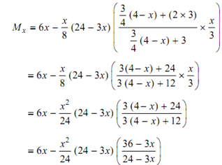
          = 6x-( x2/24)(36-3x)

          = 6x- (3x2/24)-(3x3/24)

         Mx = 6x - (3x2/2)-(x3/8)

This equation denoted that the bending moment diagram is in the form of cubic curve.


Related Discussions:- Simply supported beam - shear force diagram

Evaluate the speed of wheel, In an epicyclic gear train, the internal wheel...

In an epicyclic gear train, the internal wheels B and A and compound wheels C and D rotate independently about axis O. The wheels E and F rotate on pins fixed to the arm G. E gear

Determine initial tension in the belt, A flat belt, 8 mm thick and 100 mm w...

A flat belt, 8 mm thick and 100 mm wide transmits power between two pulleys, running at 1600 m/min. The mass of the belt is 0.9 kg/m length. The angle of lap in the smaller pulle

Relation between stress and strain, Relation between stress and strain: ...

Relation between stress and strain: The relation between stress and strain is generally shown by plotting a stress-strain (σ -e) diagram. Stress can be plotted on ordinate (ve

State Initial graphics exchange specifications, Initial Graphics Exchange S...

Initial Graphics Exchange Specifications (IGES) The basic concept of IGES is concerned with the exchange of product description data from one CAD system to another one. The CAD

Machine design 1, Our sir asked us to design a knuckle joint...they gave us...

Our sir asked us to design a knuckle joint...they gave us only the tensile force applied on the joint as 50kn...and told us to find the appropriate material..so what can we use???

Find minimum thickness, A 1.2 m diameter steel pipe carries oil of relative...

A 1.2 m diameter steel pipe carries oil of relative density 0.822 under a head of 70 m of oil. What minimum thickness of 120 MPa (yield stress) steel would be required for a safety

Subsea Valves, Read two documents that will provide and answer the followin...

Read two documents that will provide and answer the following questions: 1) You will note from reading the above referenced specifications that fewer valve types are recommended fo

Find the magnitude and position of maximum bending moment, A simply support...

A simply supported beam of length 5m takes a uniformly increasing load of 800 N/m at one end to 1600 N/m at the other end. Draw the shear force and the Bending moment diagrams for

Special casting methods, Special Casting Methods: 1. Die casting : D...

Special Casting Methods: 1. Die casting : Die casting is a permanent mould casting techniques in which molten metal is forced in the mould cavity under a pressure of 700 to

Break mean effective pressure - thermodynamics, Brea k Mean Effective Pr...

Brea k Mean Effective Pressure (P bm ): Likewise, the brake mean effective pressure is given by   i p       = indicated power (kW) bp     = Break Powder (kW

Write Your Message!

Captcha
Free Assignment Quote

Assured A++ Grade

Get guaranteed satisfaction & time on delivery in every assignment order you paid with us! We ensure premium quality solution document along with free turntin report!

All rights reserved! Copyrights ©2019-2020 ExpertsMind IT Educational Pvt Ltd