Resultant of non-coplanar force system, Mechanical Engineering

Assignment Help:

Resultant of Non-coplanar Force System:

The resultant of a system of coplanar forces can be attained by adding up two forces through law of parallelogram at a time and after that combining their sums.

Analytically, the similar result can be obtained by forming the rectangular components of the forces along with any two convenient perpendicular directions. The magnitude and the direction of the consequential are found in the same way as that given for the concurrent forces, i.e.


1156_Resultant of Non-coplanar Force System.png

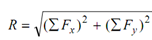
                                tan θx  = ∑ Fy / ∑ Fx

The position of the line of action of R can be computed with the help of Varignon's theorem.

In particular case of non-coplanar forces, there can be parallel or non-parallel system of forces. In particular case of parallel forces, the resultant can be  (i) a single force R parallel to the system of forces, (ii) a couple in the plane of the system or in a parallel plane, or (iii) zero.

R = Σ F and it is parallel to the line of action of forces.

If          R ≠ 0 then the location of the line of action of the forces may be found out by

R × d = ∑ M o

Here,   d = perpendicular distance through the moment centre to the resultant R,

Σ Mo = algebraic addition of the moments of all of the forces w.r.t. the point under reference.

If Σ F = 0, the resultant can consist of a couple of magnitude Σ Mo.

Σ F = 0 and Σ Mo = 0, after that the resultant is zero.

For non-parallel forces, the resultant can be (a) a single force R (b) a couple, M, or (c) single force R and a couple M. In general, this is a combination of a force and a couple.

The resultant of any general force system may be attained by resolving each force into a parallel force through some of the common points and a couple. Therefore, the system is decreased to a set of concurrent forces and a set of couples. The resultant of concurrent force system may be attained by resolving the force into three mutually perpendicular axes system, x, y and z axis. Therefore, we obtain

2421_Resultant of Non-coplanar Force System1.png

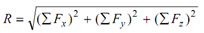
cos θx = ∑ Fx / R, cos θ y =∑ Fy / R cos θz = ∑ Fz/ R

where ∑ Fx , ∑ Fy  and ∑ Fz are the algebraic sums of the components of all of the forces along with x, y and z axes, respectively. The angles θx, θy and θz are the angles that the resultant R makes respectively with x, y and z axes.


Related Discussions:- Resultant of non-coplanar force system

Compressive strength, I have some plastic tube .5 OD .44 ID .5 long I put t...

I have some plastic tube .5 OD .44 ID .5 long I put them in a vise end to end (sealing the inside of the tube) THen using a torque wench crush them to see when they fail. I get rea

Time and cost analysis, Time and Cost Analysis This discusses about ce...

Time and Cost Analysis This discusses about certain basic activities that must be carried out in a factory to convert raw materials into finished products. These activities br

#title.kaplan turbine., #q(b) Illustrate governing mechanism of Kaplan turb...

#q(b) Illustrate governing mechanism of Kaplan turbine.uestion..

Define application of drilling machine, Application of Drilling machine ...

Application of Drilling machine Drilling machines of dissimilar capacity and configuration are basically used for originating cylindrical holes and occasionally for enlarging t

Method of section, Method of section: Define the method of section? H...

Method of section: Define the method of section? How can you solve the problems with the help of method of section? Sol.: This method is powerful method for determining

Define yoke or magnetic frame - dc generator, Yoke or magnetic frame It...

Yoke or magnetic frame It is the outer cover of the machine. An even number of pole cores are bolted to the yoke. Its serves the following purposes 1. It gives mechanical su

Determine the load on beam, Determine the load on beam: A rectangular ...

Determine the load on beam: A rectangular beam of width 200 mm and depth 300 mm is simply supported over a span of 5 m. determine the load that the beam may carry per metre le

Design of connecting rod, Design of Connecting Rod: Design and analyse...

Design of Connecting Rod: Design and analyse the stress distribution in a connecting rod as shown in Figure 5. The axial load which the connecting rod carries is 1kN and the m

What is the use of ball race drive, (a) What is the use of ball race drive?...

(a) What is the use of ball race drive? (b) How should one install the bottom cone race? (c) What is the use of front fork oil seal driver body and its attachment? (d) Wha

Write Your Message!

Captcha
Free Assignment Quote

Assured A++ Grade

Get guaranteed satisfaction & time on delivery in every assignment order you paid with us! We ensure premium quality solution document along with free turntin report!

All rights reserved! Copyrights ©2019-2020 ExpertsMind IT Educational Pvt Ltd