Resultant of coplanar concurrent force system, Mechanical Engineering

Assignment Help:

Resultant of coplanar concurrent force system:

The resultant force, of given system of forces can be found out by the resolution method, which is discussed below:

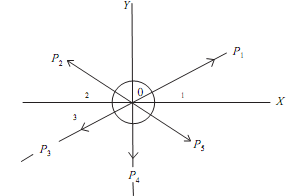
Assume the forces be P1P2P3P4, and P5 acting at 'o'. Let OX and OY be the two perpendicular directions. Let the forces subtend angle a1, a2, a3, a4, and a5 with Ox respectively. Let R be the resultant and inclined at the angle with OX.

Resolved part of 'R' along OX = Sum of the resolved parts of P1, P2, P3, P4, P5 along OX.
16_Resultant of coplanar concurrent force system.png

That is

Resolve all the forces horizontally and find algebraic sum of all horizontal components

(which is ∑H)

1683_Resultant of coplanar concurrent force system1.png 

Resolve all the forces in vertical direction and find the algebraic sum of all the vertical components (that is, ∑V)

1808_Resultant of coplanar concurrent force system2.png 

The resultant R of given forces can be given by equation:

769_Resultant of coplanar concurrent force system3.png  407_Resultant of coplanar concurrent force system4.png 

And the resultant force will be inclined at the angle 'θ' with the horizontal, so that

                                                               tanθ = ∑V/∑H 


Related Discussions:- Resultant of coplanar concurrent force system

Illustrate the structure of set, Illustrate the structure of SET SET al...

Illustrate the structure of SET SET allows the exchange of data between different CAD/CAM systems and also between CAD/CAM systems and central data banks. It features a much mo

Explain the methodology of hydrostatic sensor pavers machine, Normal 0 ...

Normal 0 false false false EN-IN X-NONE X-NONE MicrosoftInternetExplorer4 Explain the Methodol

Pyrolysis-manufacturing methods of ceramics, Pyrolysis Pyrolysis is th...

Pyrolysis Pyrolysis is the procedure of depositing a ceramic on a heated substrate. The process is used to deposit coating or generate thin walled components of graphite or si

#, parameters in designing a presure vessels

parameters in designing a presure vessels

Head loss, calculate the head required

calculate the head required

Magnetic susceptibility and ferromagnetic substances, Magnetic Susceptibili...

Magnetic Susceptibility and Ferromagnetic Substances: Magnetic Susceptibility: The magnetic susceptibility (c) of a substance is defined  as the ratio of the intensity of magn

Cross belt drive, Cross Belt Drive: When shafts are rotating in the o...

Cross Belt Drive: When shafts are rotating in the opposite direction, cross belt drive can be obtained. Figure In the diagram given to us pulley 'A' is called as

Evaluate the acceleration of the three weights, Evaluate the acceleration o...

Evaluate the acceleration of the three weights: A system of weight connected by the string passing over pulleys A and B is shown in figure given below. Find out acceleration

Determine the support reactions, Determine the Support Reactions The p...

Determine the Support Reactions The pin-connected structure shown is supported by a fixed (frictionless) pin at A and by a roller at E . A 3-kN vertical force is applied at F

I-Section, An unsymmetrical I-Section as shown in figure below. If maximum ...

An unsymmetrical I-Section as shown in figure below. If maximum bending stress is not extend more than 40MPa in the section than find out the moment which it can bear

Write Your Message!

Captcha
Free Assignment Quote

Assured A++ Grade

Get guaranteed satisfaction & time on delivery in every assignment order you paid with us! We ensure premium quality solution document along with free turntin report!

All rights reserved! Copyrights ©2019-2020 ExpertsMind IT Educational Pvt Ltd
