Power angle and performance characteristics, Electrical Engineering

Assignment Help:

Q. Power Angle and Performance Characteristics?

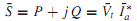
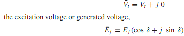
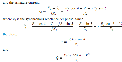
The real and reactive power delivered by a synchronous generator, or received by a synchronous motor, can be expressed in terms of the terminal voltage Vt, the generated voltage Ef, the synchronous impedance Zs, and the power angle or torque angle δ. Referring to Figure, it is convenient to adopt a convention that makes positive the real power P and the reactive power Q delivered by an overexcited generator. Accordingly, the generator action corresponds to positive values of δ, whereas the motor action corresponds to negative values of δ. With the adopted notation it follows that P > 0 for generator operation, whereas P< 0 for motor operation. Further, positiveQmeans delivering inductiveVARs for a generator action, or receiving inductive VARs for a motor action; negative Q means delivering capacitive VARs for a generator action, or receiving capacitive VARs for a motor action. It can be observed from Figure that the power factor is lagging when P and Q have the same sign, and leading when P and Q have opposite signs.

2025_Power Angle and Performance Characteristics3.png

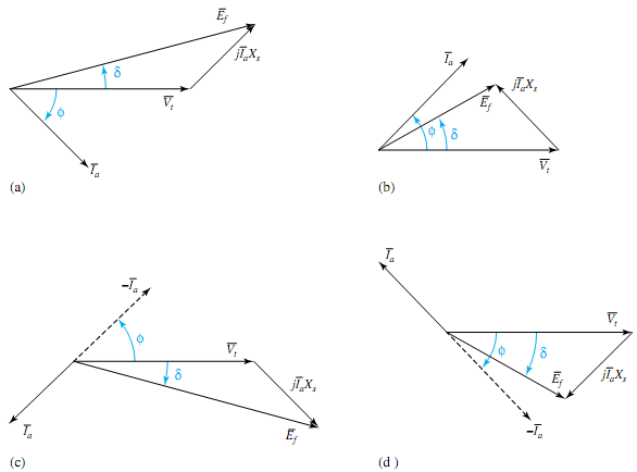
The complex power output of the generator in volt-amperes per phase is given by

1404_Power Angle and Performance Characteristics.png

where ¯Vt is the terminal voltage per phase, ¯Ia is the armature current per phase, and * indicates a complex conjugate. Referring to Figure (a), in which the effect of armature resistance has been neglected, and taking the terminal voltage as reference, we have the terminal voltage,

696_Power Angle and Performance Characteristics1.png

1727_Power Angle and Performance Characteristics2.png

Equations hold for a cylindrical-rotor synchronous generatorwith negligible armature resistance. To obtain the total power for a three-phase generator, Equations should be multiplied by 3 when the voltages are line to neutral. If the line-to-line magnitudes are used for the voltages, however, these equations give the total three-phase power.


Related Discussions:- Power angle and performance characteristics

What is the function of ct and p.t, Q. What is the function of CT and P.T a...

Q. What is the function of CT and P.T and where they are used? Ans: The full form of CT is Current transformer and is used for calculating of current. The full form of PT is

Automotive industry, The worldwide automotive industry is currently witness...

The worldwide automotive industry is currently witnessing rapid innovative developments day by day. The developments encompass every aspect of the automobile such as materials, man

Produce electrical power using solar cell - electrical power, 1. Suppose th...

1. Suppose the California government sets aside a square patch of land that is 10 kilometers on each side and plans to use this land to generate electrical power with wind turbines

Datapath and a datapath logic cell, Explain what is meant by a datapath and...

Explain what is meant by a datapath and a datapath logic cell illustrating your answer by reference to a suitable function using diagrams as appropriate. Show using a diagram ho

8 bit data to register - move immediate instruction , 8 bit  data to Regi...

8 bit  data to Register   This form  of the  instruction is used to copy 8 bit  data directly  to the register  location specified in  the instruction. The  instruction format i

Stakeholders - legal requirements for distribution licensees, Stakeholders ...

Stakeholders - Legal Requirements for Distribution licensees There have to be consultations among several stakeholders such as the licensees, the governments, consumers, gener

Complete the timing diagram for counter, Q. When the J and K inputs of a JK...

Q. When the J and K inputs of a JKFF are tied to logic 1, this device is known as a divide-by-2 counter. Complete the timing diagram shown in Figure for this counter.

Explain the applications of emitter follower, Q. Explain the applications o...

Q. Explain the applications of emitter follower. Because of high input impedance and low output impedance an emitter follower is capable of transferring maximum power from the

Frequency modulation, 1. Frequency Modulation theory and its explanation ...

1. Frequency Modulation theory and its explanation 2. FM transmitter schematic, tests results and measurements 3. Amplifier and Oscillator circuit explanation and calculation

Determine the induced voltage at full load, A 100-kW, 250-V shunt generator...

A 100-kW, 250-V shunt generator has an armature-circuit resistance of 0.05  and a field- circuit resistance of 60 . With the generator operating at rated voltage, determine the i

Write Your Message!

Captcha
Free Assignment Quote

Assured A++ Grade

Get guaranteed satisfaction & time on delivery in every assignment order you paid with us! We ensure premium quality solution document along with free turntin report!

All rights reserved! Copyrights ©2019-2020 ExpertsMind IT Educational Pvt Ltd