Explain working of cardiac pacemaker, Electrical Engineering

Assignment Help:

Q. Explain working of Cardiac Pacemaker?

When blockage occurs to the biological signals that stimulate the heart to beat, the application of electric pacemaker pulses forcing the heart to beat at a higher rate is very helpful. A demand pacemaker is particularly helpful to the patient with partial blockage, in which case an electric pulse to the heart muscle is only applied when a beat does not occur within a predetermined time interval.

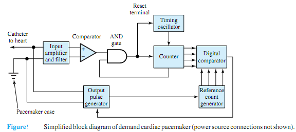
The pacemaker circuitry along with a lithium battery are enclosed in a metal case, which is implanted under the skin on the patient's chest. The mental case and the tip of the catheter (a wire enclosed in an insulating tube) form the electrical terminals of the pacemaker. A simplified block diagram of a typical demand pacemaker is shown in Figure.

The input amplifier amplifies the natural heart signals, which have a small amplitude on the order of 1 mV. Filtering eliminates certain frequency components so that heartbeats can be better detected. A comparative circuit is then used to compare the amplified and filtered signal with a threshold value and detect either a natural heartbeat or an output pacing pulse. This detection decision is passed on to the counting and timing circuitry through an AND gate. The second input to the AND gate comes from the counter circuit, such that input signals for 0.4 s after the start of a natural or forced beat are ignored.

The timing functions are performed by counting the output cycles of a timing oscillator, which generates a square wave with a precise period of 0.1 s. The digital signals produced by the counter are passed on to a digital comparator, which compares them with signals from a reference count generator and decides when the pulse generator is to deliver an output pulse of a specified amplitude and duration.

1699_Cardiac Pacemaker.png

Extremely low power consumption and high reliability become important criteria for all pacemaker designs.While electrical engineers can come upwith better circuit designs,mechanical and chemical engineers have to select better materials to produce the case and the catheter, and above all, the physicians have to provide the pacemaker specifications.Thus, doctors and engineers have to work in teams in order to develop better biomedical products.


Related Discussions:- Explain working of cardiac pacemaker

Features and usage of peripheral component interconnect bus, Discuss featur...

Discuss features and usage of Peripheral Component Interconnect bus. Peripheral Component Interconnect bus has plug as well as play characteristics and the capability to func

Determine the form factor and peak factor, Determine the form factor and pe...

Determine the form factor and peak factor: Determine the form factor and peak factor for the above half rectified wave. Solution From the above example, I rms   =

Coupling, advantages and disadvantages of direct and r c coupling

advantages and disadvantages of direct and r c coupling

When both mt2 and gate are negative, When both MT 2 and Gate  are Negativ...

When both MT 2 and Gate  are Negative In this case N 3   works as a remote gate. Current  flows form layer P 2 to layer  N 3 junction N 1 P 1 is reverse biased  and it  br

Dc machines, singly excited magnetic systems

singly excited magnetic systems

Explain the alphanumeric coding - bcd to decimal conversion, Explain the Al...

Explain the Alphanumeric Coding - bcd to decimal conversion? For the inherently binary world of computer, it is necessary to put all symbols, letters, numbers, and so on into bin

What is expanded memory system, What is expanded memory system? EMS: Th...

What is expanded memory system? EMS: The area at location C8000H-DFFFFFH is frequently open or free. Such area is used for the expanded memory system into a XT or PC system, or

Calculate motor efficiency, 1. A self excited shunt generator supplies a lo...

1. A self excited shunt generator supplies a load of 12.5 kw at 125 volts. The field resistance is 25 ohms and the armature resistance is 0.2 ohms. The total voltage drop because o

Telecommunication, Design a low noise amplifier using an Infineon RF transi...

Design a low noise amplifier using an Infineon RF transistor BFP640. The amplifier is to be used to amplify the L2 GPS signal and so the centre frequency is 1227MHz and bandwidth 4

Write Your Message!

Captcha
Free Assignment Quote

Assured A++ Grade

Get guaranteed satisfaction & time on delivery in every assignment order you paid with us! We ensure premium quality solution document along with free turntin report!

All rights reserved! Copyrights ©2019-2020 ExpertsMind IT Educational Pvt Ltd