Explain error-rate control and output-rate control, Electrical Engineering

Assignment Help:

Error-Rate Control, Output-Rate Control, and Integral-Error (Reset) Control

Let us consider a typical second-order servomechanism(containing two energy-storing elements) whose defining differential equation for obtaining the dynamic behavior of the system is given by

2338_Error-Rate Control and Output-Rate Control.png

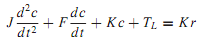
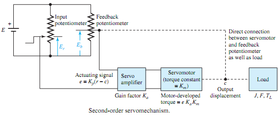
where J, F, and TL represent, respectively, effective inertia, equivalent viscous friction, and resultant load torque appearing at the motor shaft; K = KpKaKm, where Kp is the potentiometer transducer constant (V/rad), Ka is the amplifier gain factor (V/V), and Km is the motor-developed torque constant (N·m/V) of the physical servomechanism shown in Figure; r is the input command and c is the output displacement, both in radians.

The block diagram of the servomechanism of Figure is given in Figure, in which the transfer function of each component is shown. Since the actuating signal is given by E = Kp(R - C), the block diagram may be simplified, as shown in Figure, in which TL is assumed to be zero for simplicity. The direct transmission function (forward path transfer function) for the system can be seen to be

2419_Error-Rate Control and Output-Rate Control1.png

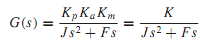
The corresponding closed-loop transfer function is given by


555_Error-Rate Control and Output-Rate Control2.png

882_Error-Rate Control and Output-Rate Control3.png


Related Discussions:- Explain error-rate control and output-rate control

Sinusoidal steady-state phasor analysis, Q. Sinusoidal steady-state phasor ...

Q. Sinusoidal steady-state phasor analysis? The kind of response of a physical system in an applied excitation depends in general on the type of excitation, the elements in the

What is capacitance, What is Capacitance -  Capacitance is explained to...

What is Capacitance -  Capacitance is explained to be the amount of charge Q stored in among the two plates for a potential difference or voltage V existing across the plates.

Block diagram and the truth table of a demultiplexer, Q. Given the block di...

Q. Given the block diagram and the truth table of a demultiplexer, as shown in Figure, obtain its implementation.

Dc motor control, how thyristor work in speed control??

how thyristor work in speed control??

Discuss endp assembler directive, Discuss the ENDP assembler directive ...

Discuss the ENDP assembler directive with example ENDP: It is stands for End Procedure, which informs assembler the end of a procedure. Within assembly language programm

Determine voltage in given figure, Q. An n-channel JFET having V P = 3.5 V...

Q. An n-channel JFET having V P = 3.5 V and I DSS = 5 mA is biased by the circuit of Figure with V DD = 28 V, RS = 3000 , and R 2 = 100 k. If the operating point is given by

Digital control system, block diagram of digital control system and explain...

block diagram of digital control system and explain each block

#title.Shockley diode, I want proof of shockley diode equation with all ste...

I want proof of shockley diode equation with all steps

Digital communications system, Question 1 (a) Describe the functions of...

Question 1 (a) Describe the functions of the modulator and source encoder in a digital communications system. (b) By using appropriate examples, distinguish between th

Write Your Message!

Captcha
Free Assignment Quote

Assured A++ Grade

Get guaranteed satisfaction & time on delivery in every assignment order you paid with us! We ensure premium quality solution document along with free turntin report!

All rights reserved! Copyrights ©2019-2020 ExpertsMind IT Educational Pvt Ltd