Determine the total active power, Electrical Engineering

Assignment Help:

Determine the total active power:

Circuit is introduced in the Face 1. It is about a single-wires face for a three-phase system. The voltage of the AC source is of 69kV. The source is a balanced source of 60 Hz.The voltage phasor of phase ahasa zero angle:VPhase a = (69/√3) 0o.

1155_total active power.png

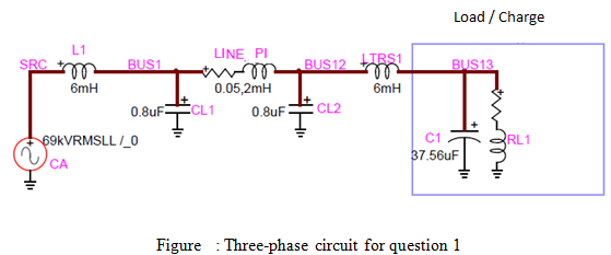
For a given load RL1, we obtain the following three currents for the AC source.The currents are measured so that the direction of the currents is from the bar SRC towards the ground (neutral) but not towards the bar BUS1. The board below indicates values crests


Module (A)

Phase (degre)

SRCa

1.844847 x 10³

1.5325 x 10²

SRCb

1.844847 x 10³

3.325 x 101

SRCc

1.844847 x 10³

- 8.675 x 101

1-Is the circuit seen by the source balanced? Explain why.

2-Calculate the total apparent power S (expressed in phasor) produced (from the source to the circuit) by the three-phase source. Feel free to use the shortest way of calculation.

3-What is the total active power (P) produced by the three-phase source?

4-What is the total reactive power (Q) produced by the three-phase source?

5-What is the power factor of the circuit seen by the source?

6-Calculate the voltages (phasors, line-neutral) of phases a, b and c in the bar BUS1.

7. Calculate the voltage phasor of direct sequence (line-neutral) in the bar BUS1.

8-Calculate the voltage phasorof homopolarsequence in the barBUS1

9-Calculate the impedance of direct sequence at 60 Hz seen by the source.


Related Discussions:- Determine the total active power

Magnetic circuits, Suppose we have a coil wound onto a ring of material wit...

Suppose we have a coil wound onto a ring of material with relative permeability µ r . Provided that the relative permeability µ r  >> 1, then the magnetic flux lines will s

Digital circuits, Digital circuits In analog  circuits,  we think  som...

Digital circuits In analog  circuits,  we think  something about  voltages on terminals ranging over natural values.  This provides us the freedom to make an enormous variety

Loops and subroutines, 1.....If viewing this through the Assignment tool, c...

1.....If viewing this through the Assignment tool, click the title above to go to the Submissions area. Introduction The purpose of this experiment is to examine the opera

.energy, units of potential energy

units of potential energy

Power and power distribution, design a single phase distribution circuit fr...

design a single phase distribution circuit from a supply point to a load

#title.Shockley diode, I want proof of shockley diode equation with all ste...

I want proof of shockley diode equation with all steps

Electronics, why bypass capacitor is used

why bypass capacitor is used

Describe small signal fet and its characteristics, Q. Describe small signal...

Q. Describe small signal FET.What are its characteristics? Small signal FET is the FETs used for amplification. The linear characteristic of FET is used for this purpose The in

Write Your Message!

Captcha
Free Assignment Quote

Assured A++ Grade

Get guaranteed satisfaction & time on delivery in every assignment order you paid with us! We ensure premium quality solution document along with free turntin report!

All rights reserved! Copyrights ©2019-2020 ExpertsMind IT Educational Pvt Ltd