Determine potential difference across resistor, Electrical Engineering

Assignment Help:

Determine Potential Difference:

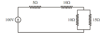
Compute the current through each element of the given network and also determine potential difference across 15 Ω resistor.

738_Determine Potential Difference.png

Figure

Solution

The circuit may be reduced in the following form :

Figure

Total current i in the circuit is achieved by

 i = V/ R = 100 /(5 + 10 + 6) = 100 /21= 4.76 Amp

So the current through 5 Ω and 10 Ω resistor shall be i = 4.76 Amp.

Now, current through 10 Ω resistor in parallel branch is find out by current division rule :

i1 = i × (r2 / (r1 + r2))

= 4.76 × (15 / (10 + 15)) = 2.85 Amp

Likewise, current through 15 Ω resistor is

i2  = i × (10 / (r1 + r2))

= 4.76 × (10 /(10 + 15))

= 1.9 Amp

∴Potential difference across 15 Ω resistor shall be

 V = i2  × 15= 1.9 × 15 = 28.5 volts


Related Discussions:- Determine potential difference across resistor

Draw and explain colpitts oscillator, Q. Draw and explain Colpitts oscillat...

Q. Draw and explain Colpitts oscillator? Colpitt's oscillator is a superb circuit which is used widely in commercial signal generations of  frequency of 100 Mhz . It consists o

What are the duties of sub-station operator, What are the Basic Duties of S...

What are the Basic Duties of Sub-Station Operator? Ans: Sub station operator is responsible for safe and proper operation of all electrical equipments in sub-station. He co

..analong course design, Askhigh precision linear amplifier question #Mini...

Askhigh precision linear amplifier question #Minimum 100 words accepted#

Variation of energy bands with alloy composition, Variation of Energy Bands...

Variation of Energy Bands with Alloy Composition The  band  structures  of  III-V  ternary  and  quaternary  compounds  modifies  as  their composition is varied. There

#t voice controlled mobile base, The aim of this project is to design, co...

The aim of this project is to design, construct and build a motorised base driven by two small dc motors. The motor drives are two H-bridges. The switching devices in these bridges

Dc machines, how unbalanced effect in wave winding is considered to be bala...

how unbalanced effect in wave winding is considered to be balanced?

Plot the waveforms of the inductor current, Q. The current through a 2.5-mH...

Q. The current through a 2.5-mH indicator is a damped sine given by i(t) = 10 e -500t sin 2000t. With the aid of MATLAB, plot the waveforms of the inductor current i(t), with v

Polarisation, describe the working and construction diagram of nicholas pri...

describe the working and construction diagram of nicholas prism

Define the objectives of load flow analysis, Define the Objectives of Load ...

Define the Objectives of Load Flow Analysis The objectives of load flow analysis are: (i) To analyse an existing power system, future expansion or a new power system plan.

Write Your Message!

Captcha
Free Assignment Quote

Assured A++ Grade

Get guaranteed satisfaction & time on delivery in every assignment order you paid with us! We ensure premium quality solution document along with free turntin report!

All rights reserved! Copyrights ©2019-2020 ExpertsMind IT Educational Pvt Ltd