Determine the maximum bending stresses, Mechanical Engineering

Assignment Help:

Determine the maximum bending stresses:

A rectangular beam of breadth 100 mm & depth 200 mm is simply supported over a span of 4 m. The beam is loaded with a uniformly distributed load of 5 kN/m over the whole span. Determine the maximum bending stresses.

Solution

Breadth of beam, b = 100 mm

Depth of beam, d = 200 mm

Moment of inertia, I =1 /12 bd3 = ( 1/12 )× 100 × (200)3 = 66.67 × 106 mm4

Span of beam, I = 4 m

Uniformly distributed load, w = 5 kN/m

Maximum bending moment at centre of beam,

M = wl 2/8  =5 × 4 2/8

= 10 kN m = 107 N mm

761_Determine the maximum bending stresses.png

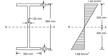
(1)   Cross-section of Beam                    (2) Bending Stress Distribution

Figure

Neutral axis passes by the centre of section.

The distance of top and bottom layer from neutral axis, y = 100 mm

Thus, Bending stress, σ = (M/ I) × y

= (107 )/(66.67 × 106) × 100

= 15 N/mm2

Thus the extreme bending stresses are 15 N/mm2. Figure illustrated the bending stress distribution for this rectangular section.


Related Discussions:- Determine the maximum bending stresses

Huckel theory - quantum and spectroscopy, (1) Huckel Theory: Using Huckel t...

(1) Huckel Theory: Using Huckel theory, write a program that solves for the molecular orbitals and energy levels in a conjugated or aromatic hydrocarbon (i.e. ethylene, butadiene,

Cylinder head de-carburising and valve lapping, Cylinder Head De-carburisin...

Cylinder Head De-carburising and Valve Lapping: Cylinder head mounts on the top of the engine cylinder, the inner side of the cylinder head is always in direct contact of combusti

Question.., Two concentric perforared plates are seperated by a 200mm laund...

Two concentric perforared plates are seperated by a 200mm launder and form the flow exit for a clarifier (figure 1). The inlet water flow of 1200 mcubed/hour into the clarifier is

Load diagram - shear force and bending moment, Loa d Diagram and BM D f...

Loa d Diagram and BM D fro m the Given SF D: Q: Shear force diagram of simply supported beam is given in the figure below.  Calculate the support reactions of beam and

Land fill bio gas, working principle of land fill bio gas plant

working principle of land fill bio gas plant

[email protected], how i can know moulair plant calculation?

how i can know moulair plant calculation?

Determination of wind-induced forces on pressure vessels, Q. Determination ...

Q. Determination of Wind-Induced Forces on Pressure Vessels? ASCE does not provide the complete methodology needed to account for wind-induced forces on common appurtenances to

Structures of materials, what is the difference between atomic structure an...

what is the difference between atomic structure and crystal structure

Spot welding of different metals-nickel and monel metal, Spot welding of di...

Spot welding of different metals-Nickel and monel metal While spot welding these materials, the settings are to be properly maintained. Welding time, in this case, is only 50 %

Write Your Message!

Captcha
Free Assignment Quote

Assured A++ Grade

Get guaranteed satisfaction & time on delivery in every assignment order you paid with us! We ensure premium quality solution document along with free turntin report!

All rights reserved! Copyrights ©2019-2020 ExpertsMind IT Educational Pvt Ltd