Determine moment of this normal force - rectangular beam, Mechanical Engineering

Assignment Help:

Determine moment of this normal force - rectangular beam:

A rectangular beam contains a width of 100 mm and a depth of 200 mm. This is utilized as a simply supported beam & the maximum bending stress is restricted to 10 N/mm2. Then determine the following :

 (a) Entire normal force on the left bottom corner area of size 40 mm × 60 mm, and

(b) moment of this normal force around the neutral axis.

Solution

Maximum bending stress, σmax = 10 N/mm2

Normal force on the shaded area, left bottom corner  is following

708_Determine moment of this normal force.png

=   (10/100) × (40 × 60) × (40 + 30)

Here, A = Shaded area = 40 × 60 mm2

1894_Determine moment of this normal force1.png =   Centroid of shaded area through the neutral axis

= (100 - 60) + ( 60/2) = (40 + 30) = 70 mm
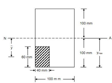
74_Determine moment of this normal force2.png

Figure

∴ Normal force on the partial beam section is following

 =   (10/100) × 2400 × 70 = 16800 N = 16.8 N

The partial area is subjected into a tensile force

∴ Normal force on partial beam section = 16.8 kN (tension)

Moment of the force around the neutral axis

= (σmax / ymax) × Is

Is = Moment of inertial of the shaded area around the neutral axis

=   (1/12)  × 40 × (60)3  + (40 × 60) × (70)2  = 1248 × 104  mm4

∴ Moment of normal force around the neutral axis

=  ( 10 /100) × 1248 × 104  = 1248 × 103  Nm = 1248 m


Related Discussions:- Determine moment of this normal force - rectangular beam

Nozzle design loads, Q. Nozzle Design Loads? Minimum nozzle design load...

Q. Nozzle Design Loads? Minimum nozzle design loads shall be in accordance. F = Axial force on centre line of nozzle (lbs); Maximum Transverse Force =1.5F F R = Resultan

Calculate the magnitude of maximum bending moment, Calculate the magnitude ...

Calculate the magnitude of maximum bending moment: The shear force diagram for the overhanging beam is illustrated in Figure. Draw the loading diagram & bending moment diagram

Deflection at the centre - simply supported beam, Deflection at the centre:...

Deflection at the centre: A simply supported beam of span 6 m is subjected to Udl of 24 kN/m for a length of 2 m from left support. Discover the deflection at the centre, maxi

Differentiate between dynamometer and brakes, Can you Differentiate between...

Can you Differentiate between : Dynamometer and Brakes. Absorption Dynamometer and Transmission Dynamometer.

How to calculate coupling factor?, Q. Two coils with self inductances 1H an...

Q. Two coils with self inductances 1H and 4H have a mutual inductance of 1H. The RMS value of current flowing in the two coils is 4A and 1A respectively. Find  the coupling factor

What do you mean by risers and downcomers, Q. What do you mean by Risers an...

Q. What do you mean by Risers and Downcomers? Risers and downcomers shall be staggered along the shell of the WHB and steam drum for uniform water/steam circulation in the syst

Counter flow and parallel flow heat exchange, What is the difference betwee...

What is the difference between counter flow and parallel flow Heat exchange. Classify Heat exchange on the basis of constructional features and design.

What do you mean by turret nozzle, Q. What do you mean by turret Nozzle? ...

Q. What do you mean by turret Nozzle? Turret Nozzle - Turret nozzles are large nozzles that can deliver large quantities of water quickly. They are used on very large fires whe

Thermodynamics, Energy in state and it''s transition

Energy in state and it''s transitions

Write Your Message!

Captcha
Free Assignment Quote

Assured A++ Grade

Get guaranteed satisfaction & time on delivery in every assignment order you paid with us! We ensure premium quality solution document along with free turntin report!

All rights reserved! Copyrights ©2019-2020 ExpertsMind IT Educational Pvt Ltd