Determine maximum fibre stress - beam, Mechanical Engineering

Assignment Help:

Determine Maximum fibre stress:

A beam of rectangular section of 80 mm to 120 mm carries a uniformly distributed load of 40 kN/m over a span of 2 m an axial compressive force of 10 kN. Determine

1.      Maximum fibre stress,

2.      Fibre stress at a point 0.50 m from the left end of the beam & 40 mm below the neutral axis.
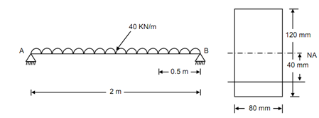
199_Determine Maximum fibre stress.png

                                     (1) Loading                                          (2) Cross-section

Figure

Solution

Bending moment, M = (w × e 2) /8= (40 × 22)/8 = 20 kN-m = 20 × 106  N-mm

Section modulus, Z = (1/6) × 80 × (120)2  = 1.92 × 10⁵  mm3

Moment of inertial, I = (1/12) × (80) × (120)3 = 11.52 × 10⁶  mm4

Axial load, P = 10 kN = 10 × 103  N

Direct stress, f0  = P/A =10 × 103/ (80 × 120) = 1.04 N/mm2

Bending stress,  f b =± M/ Z  =( 20 × 106 )/(1.92 × 105) = ± 104.16 N/mm2

∴          Maximum fibre stress = 1.04 + 104.16 = 105.20 N/mm2 (compressive)

∴          Bending moment at 0.50 m from left end will be,

M = ( - 40 × 0.50 + 40 × 0.502 / 2)

= - 15 kN-m

= 15 × 106  N-mm (sagging)

∴          Bending stress at 40 mm below the neutral axis will be,

= (M/I) . y

= (15 × 106 )/(11.52 × 106 ) × (- 40)

=- 52.08 N/mm2  (tensile)

∴          Resultant fibre stress = 1.04 - 52.08

                                             =- 51.04 N/mm2 (tensile)


Related Discussions:- Determine maximum fibre stress - beam

Constant mesh type gear box, Constant Mesh Type Gear Box : Most of the ge...

Constant Mesh Type Gear Box : Most of the gearboxes on motorcycles are "constant mesh". That means all the gears are constantly meshed with one another and are always spinning. T

Tensile stress, T ensile Stress: The stress induced in a body, when ...

T ensile Stress: The stress induced in a body, when subjected to two equal and opposite pulls as shown in figure (a) as a result of which there is an increase in length,

Cam profile, sketch and discuss the uses and application of the following t...

sketch and discuss the uses and application of the following types of cam follower;knife edge,roller and flat ended.

Mechanical efficiency, The following data were obtained from a test on a si...

The following data were obtained from a test on a single cylinder, double acting steam engine fitted with a rope brake. Cylinder diameter 200mm Stroke 250mm Speed 5rev/min Effec

Evaluate velocity of the block, Evaluate velocity of the block: A blo...

Evaluate velocity of the block: A block of 2500N rest on horizontal surface. The coefficient of friction in between block and plane is 0.3. The block can be pulled by the for

Explain match plate pattern, Match plate pattern These are extensions o...

Match plate pattern These are extensions of the previous type. Here the cope and drag patterns along with the gating and the risering are mounted on a single matching metal or

Typical joint designs used in electron beam welding, TYPICAL JOINT DESIGNS ...

TYPICAL JOINT DESIGNS THAT ARE USED IN ELECTRON BEAM WELDING Butt joint : Butt joint is the preferred joint as it involves only a small amount of machining prior to wel

Write Your Message!

Captcha
Free Assignment Quote

Assured A++ Grade

Get guaranteed satisfaction & time on delivery in every assignment order you paid with us! We ensure premium quality solution document along with free turntin report!

All rights reserved! Copyrights ©2019-2020 ExpertsMind IT Educational Pvt Ltd