Determine Impedance - Resultant current and Power factor:
In series R-L circuit, illustrated in Figure , Determine
1. Impedance,
2. Resultant current,
3. Power factor and its nature, and
4. Quality factor.
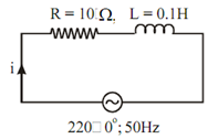
Figure
Solution
The inductive reactance XL is given by
XL = ωL
= 2π fL
= 2π × 50 × 0.1 Ω
= 31.42 Ω
The impedance in rectangular form is given by
Z = R + j X L = 10 + j 31.42 Ω
In polar form Z = 32.97 ∠ 72.345o Ω
The resultant current is given by
i = ν / Z = 220 ∠ 0o / 32.97 ∠ 72.345o
= 6.672 ∠ - 72.345o Amp.
The current is lagging (since the circuit is inductive).
The power factor angle, φ, is the angle between voltage current
φ = 72.345o (lagging)
∴ p.f. cos φ = cos (72.345o)
= 0.303 (lag)
On the other hand, the power factor may be determined by
cos φ = R/ Z
= 10 /32.97
= 0.303 (lag)
Quality factor is given by Q = 1/ cos φ = 3.3 .