Design a mod-5 synchronous counter using J-Kflip-flops, Computer Engineering

Assignment Help:

What are synchronous counters? Design a Mod-5 synchronous counter using J-K Flip-Flops.

Ans.

Synchronous Counters: It means that all flip-flops are clocked concurrently. The clock pulses drive the clock input of each flip-flop together hence there is no propagation delay.

Mod-5 Counter Synchronous Counter: This have five counter states. The counter design table for such counter shows the three flip-flop and their states also (0 to 5 states), as in table (a), the 6 inputs needed for the three flip-flops. The flip-flop inputs needed to step up the counter from the current to the next state have been worked out along with the assist of the excitation table illustrated in the table.


Input


pulse


Count

Counter States


A          B          C

Flip-Flop Inputs


JA                  KA


JB                KB                                        JC                  KC

0

0           0          0

1             X

0             X                            0              X

1

1           0          0

X             1

1             X                            0              X

2

0           1          0

1             X

X            0                           0              X

3

1           1          0

X             1

X            1                           1              X

4

0           0          1

0             X

0             X                           X             1

5(0)

0           0          0


                                                             Table (a) counter Design Table for Mod-5 Counter

A flip-flop:  The first state is 0. This change to 1 after the clock pulses. Thus JA must be 1 and KA may be 0 or 1 (i.e. X ).

B flip-flop: The first state is 0 and this keeps unchanged after the clock pulse. Thus JB must be 0 and KB may be 0 or 1 (i.e. X)

C flip-flop: The state keeps unchanged. Thus Jc must be 0 and KC must be X. The flip-flop input values are entered in Karnaugh maps demonstrated in Table (b) [(i) (ii) (iii) (iv) (v) and (vi)] and a boolean expression is determined for the inputs to the 3-flip-flops and after that each expression is simplified. All the counter states have not been utilized; X's (don't) are entered to indicate un-utilized states. For each input the simplified expressions demonstrated under each map. At last, these minimal expressions for the flip-flop inputs are utilized to illustrate a logic diagram for the counter that is demonstrated in fig. (b).

664_Karnaugh Maps for MOD-5 Synchronous Counter.png

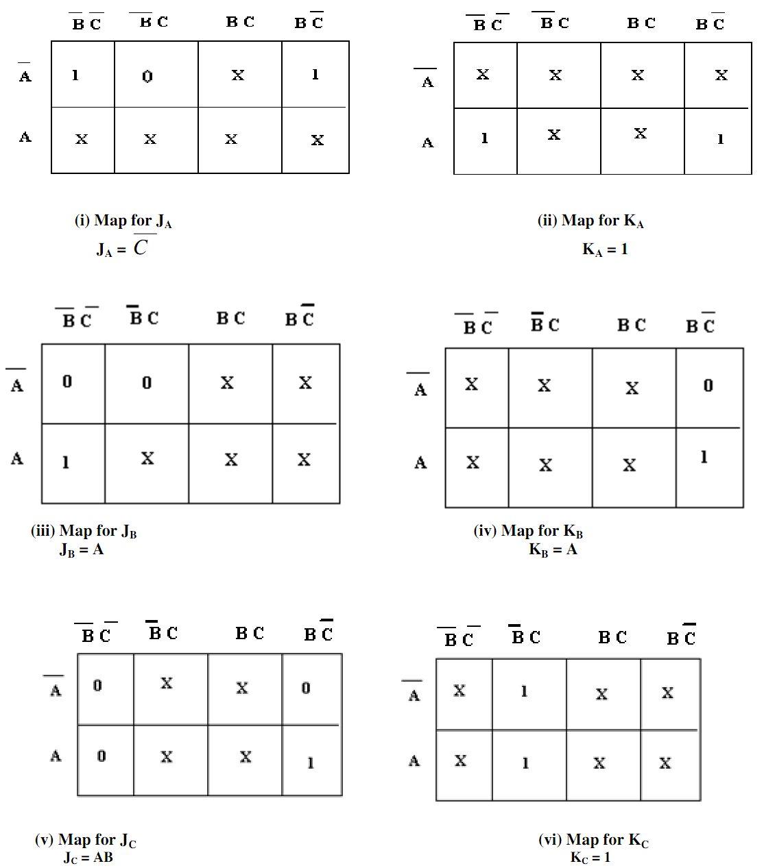
Table (b) Karnaugh Maps for MOD-5 Synchronous Counter

766_Logic Diagram of MOD-5 Synchronous Counter.png


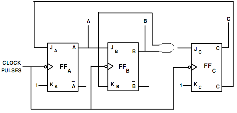
Fig. (b) Logic Diagram of MOD-5 Synchronous Counter


Related Discussions:- Design a mod-5 synchronous counter using J-Kflip-flops

#MyLife, where should I work?

where should I work?

Sigmoid units, Sigmoid units: Always remember that the function inside...

Sigmoid units: Always remember that the function inside units take as input the weighted sum, S and of the values coming from the units connected to it. However the function i

First-order inference rules, First-Order Inference Rules: Here now we ...

First-Order Inference Rules: Here now we have a clear definition of a first-order model is that we can define soundness for first-order inference rules in the same way such we

Explain about RISC pipelining, Q. Explain about RISC PIPELINING? Instru...

Q. Explain about RISC PIPELINING? Instruction pipelining is frequently used to increase performance. Let's consider this in context of RISC architecture. In case of RISC machin

Difference between top-down and bottom-up programming, What is the differen...

What is the difference between top-down and bottom-up, programming? Ans: Top-down and Bottom-up Approaches In Top-down programming approach, we begin by identifying the main

Combinational logic circuits, A circuit can be designed to perform manydiff...

A circuit can be designed to perform manydifferent functions e.g.a circuit has 3 inputs A, B and C and 3 outputs:Output X is logic level 1 (or 'high') if one or moreinputs are at l

Create simple algebraic expression from k-map, Q. Create simple algebraic e...

Q. Create simple algebraic expression from K-Map? Now create simple algebraic expression from K-Map. These expressions are created by employing adjacency if we have 2 adjacent

Define addressing modes, Define addressing modes. The dissimilar ways i...

Define addressing modes. The dissimilar ways in which the location of an operand is specified in an instruction are referred to as addressing modes.

Write Your Message!

Captcha
Free Assignment Quote

Assured A++ Grade

Get guaranteed satisfaction & time on delivery in every assignment order you paid with us! We ensure premium quality solution document along with free turntin report!

All rights reserved! Copyrights ©2019-2020 ExpertsMind IT Educational Pvt Ltd