Design a BCD to seven segment decoder that accepts a decimal digit in BCS and generates the appropriate output for segments in display indicator.
Ans:
BCD-TO-seven-Segment Decoder: A digital display which consists of seven LED segments is commonly utilized to display decimal numerals in digital systems. Various familiar illustrations are electronic calculators and watches where one 7-segment display device is utilized for displaying one numeral 0 through 9. To use this display device, the data has to be converted by some binary code to the code essential for the display. Frequently the binary code utilized is Natural BCD. Fig.(a) demonstrates the display device. Fig.(b) demonstrates the segments that should be illuminated for each of the numerals and Fig.(c) provides the display system.
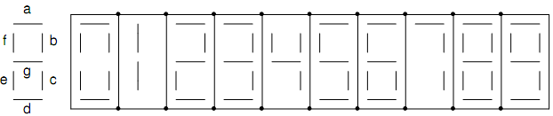
Fig.(a) Fig.(b)
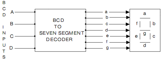
Fig.(c)
Table 1 provides the truth table of BCD-to-7-segment Decoder. Now there ABCD is the Natural BCD code for numerals 0 throughout 9. The K-maps for all of the outputs a through g are specified in Fig.(d), (f),(h),(j),(l),(n),(p). The whole in the K-map corresponding to 6 binary combinations not utilized in the truth table are X -don't care.
|
Decimal Digit
Displayed
|
|
Inputs
|
|
|
|
|
|
Outputs
|
|
|
|
|
|
A
|
B
|
C
|
D
|
a
|
b
|
c
|
d
|
e
|
f
|
g
|
|
0
|
0
|
0
|
0
|
0
|
1
|
1
|
1
|
1
|
1
|
1
|
0
|
|
1
|
0
|
0
|
0
|
1
|
0
|
1
|
1
|
0
|
0
|
0
|
0
|
|
2
|
0
|
0
|
1
|
0
|
1
|
1
|
0
|
1
|
1
|
0
|
1
|
|
3
|
0
|
0
|
1
|
1
|
1
|
1
|
1
|
1
|
0
|
0
|
1
|
|
4
|
0
|
1
|
0
|
0
|
0
|
1
|
1
|
0
|
0
|
1
|
1
|
|
5
|
0
|
1
|
0
|
1
|
1
|
0
|
1
|
1
|
0
|
1
|
1
|
|
6
|
0
|
1
|
1
|
0
|
0
|
0
|
1
|
1
|
1
|
1
|
1
|
|
7
|
0
|
1
|
1
|
1
|
1
|
1
|
1
|
0
|
0
|
0
|
0
|
|
8
|
1
|
0
|
0
|
0
|
1
|
1
|
1
|
1
|
1
|
1
|
1
|
|
9
|
1
|
0
|
0
|
1
|
1
|
1
|
1
|
0
|
0
|
1
|
1
|
Tableno.1 Truth Table of BCD-to-7 Segment Decoder
(i) K-map and Logic Diagram for Digital Output 'a':
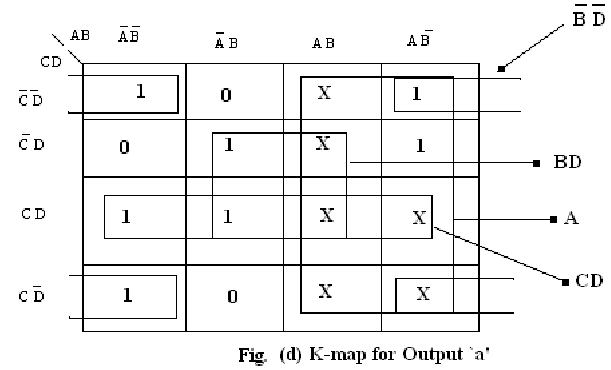
For the Fig.(d) the simplified expressions is given by a = B‾ D‾ + BD + CD + A and the logic diagram is demonstrated in Fig.(e)
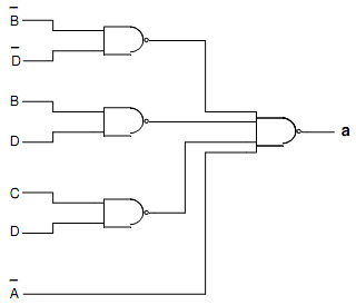
Fig.(e) Logic Diagram for Output 'a'
(ii) K-map and Logic Diagram for Digital Output 'b':
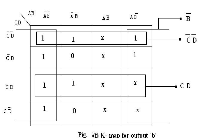
For the Fig.(f) the simplified expressions is specified by b = B‾ + C‾D‾ + CD and the logic diagram is demonstrated in Fig.(g)
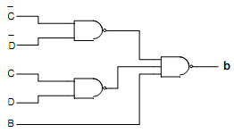
Fig.(g) Logic Diagram for Output 'b'
(iii) K-map and Logic Diagram for Digital Output 'c':
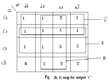
For the Fig.(h) the simplified expressions is specified by c = B + C‾ + D and the logic diagram is demonstrated in Fig.(i)
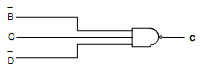
Fig.(i) Logic Diagram for Output ' c '
(iv) K-map and Logic Diagram for Digital Output'd':
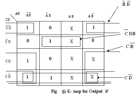
The simplified expressions for the Fig.(j) is given by
d = B‾D‾ + CD‾ + B‾C +BC‾D and the logic diagram is demonstrated in Fig.(k)
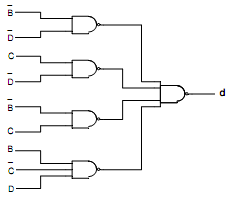
Fig.(k) Logic Diagram for Output ' d '
(v) K-map and Logic Diagram for Digital Output 'e':
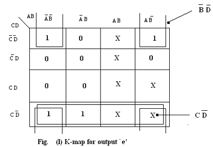
For the Fig.(l) the simplified expressions is specified by e = B‾D‾ + CD‾ and the logic diagram is demonstrated in Fig.(m)
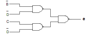
Fig.(m) Logic Diagram for Output 'e'
(vi) K-map and Logic Diagram for Digital Output 'f':
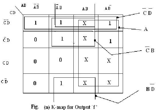
For the Fig.(n) the simplified expressions is specified by f = A + C‾ D‾ + BC‾ +BD‾ and the logic diagram is demonstrated in Fig.(o)
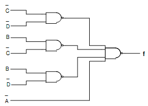
Fig.(o) Logic Diagram for Output ' f'
(vii) K-map and Logic Diagram for Digital Output 'g':
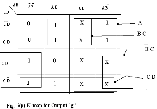
For the Fig.(p) the simplified expressions is specified by g = A + BC‾ + B‾C+ CD‾ and the logic diagram is demonstrated in fig.(q).
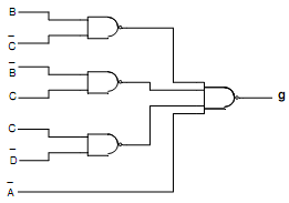
Fig.(q) Logic Diagram for Output ' g '