Describe root-finding techniques, Mechanical Engineering

Assignment Help:

In mechanics, stress is a measure of the internal forces acting within a deformable body. Quantitatively, it is a measure of the average force per unit area of a surface within the body on which internal forces act. These internal forces are produced between the particles in the body as a reaction to external forces applied on the body. In materials without microstructure (these are materials whose microstructure does not play an important role in the mechanical deformation), these internal forces are distributed continuously within the volume of the material body, and result in deformation of the body's shape. Beyond certain limits of material strength, this can lead to a permanent change of shape or physical failure. The dimension of stress is that of pressure, and therefore the SI unit for stress is the pascal (Pa).

A three-dimensional stress eld in a material can be represented as a symmetric matrix of the following form:

2448_Application to Stress Analysis1.png

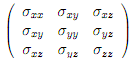
where the diagonal terms represent tensile or compressive stresses and the o -diagonal terms represent shear stresses. At every point in a stressed body there are at least three planes, called principal planes, with normal vectors called principal directions, where there are no normal shear stresses. The three stresses normal to these principal planes are called principal stresses and they are the eigenvalues of matrix (1).

To nd the principal stresses, it is necessary to construct the the following algebraic equation:

140_Application to Stress Analysis2.png

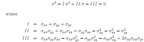
are known as the stress invariants. The roots of equation (2), 1; 2; 3, are the principal stresses.

We consider now a homogeneous material whose stress eld (in MPa) has been found experimentally to be:
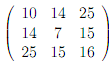
314_Application to Stress Analysis.png

We are interested in nding the principal stresses 1; 2; 3 corresponding to the given stress eld.

1. Find 1; 2; 3 using the following root- nding techniques for solving equation (2): bisection, Newton-Raphson and secant.

2. Show the pseudocode and flowchart for one of the methods.

3. Write a C++ program(s) for all three methods and compare the results.


Related Discussions:- Describe root-finding techniques

State of cad data exchange, State of CAD Data Exchange: "Are we closel...

State of CAD Data Exchange: "Are we closely there yet?" the dreaded question we hear wailing from the back of the car. "Yes, nearly there" is our cheerful response. We didn't

Calculating the number of kanban card sets, Calculating the number of kanba...

Calculating the number of kanban card sets: A hospital desires to set up a Kanban system to manage its supply of blood with the regional blood bank. The regional blood bank tr

Modulus of elasticity, Explain Young's Modulus or Modulus of elasticity? ...

Explain Young's Modulus or Modulus of elasticity? Sol. : It is ratio between tensile stress and tensile strain or compressive stress and compressive strain. It can be denote

Types of culverts - causeway and bridges, Types of Culverts: Culverts ...

Types of Culverts: Culverts are constructed with various materials and to different designs. The popular forms are : (a) Temporary stone scuppers (b) Stone slab culverts

Manufacturing process, Deferentiate between hot working and cold working p...

Deferentiate between hot working and cold working processes

Explain interpoles or commutating poles, Interpoles or commutating poles ...

Interpoles or commutating poles Interpoles are ?xed to the frame in among main poles. They are used for sparkless commutation, i.e, to improve commutation.

The ordinate dimension command-autocad, The Ordinate Dimension Command ...

The Ordinate Dimension Command We can use The Ordinate command to annotate co-ordinate points with X or Y values. This might be useful for setting-out on site plans.

Physics, difference brtween parallel and unlike parallel forces

difference brtween parallel and unlike parallel forces

The leader command-autocad, The Leader Command The Leader command can b...

The Leader Command The Leader command can be used to annotate at any point on a drawing. The command sequence below was used to draw the leader shown in the Figure Below.

Write Your Message!

Captcha
Free Assignment Quote

Assured A++ Grade

Get guaranteed satisfaction & time on delivery in every assignment order you paid with us! We ensure premium quality solution document along with free turntin report!

All rights reserved! Copyrights ©2019-2020 ExpertsMind IT Educational Pvt Ltd