Conditional branch instruction-microprocessor, Assembly Language

Assignment Help:

Conditional branch Instruction

When these type of instructions are executed, they transfer control of execution to the address mention relatively in the instruction, provided the condition implicit in the op code is satisfied, or else, the execution continues in sequence. Here, the conditions mean the status of condition code flags. These types of instructions remain unaffected from any flag. The address has to be mention in the instruction relatively in the terms of displacement which ought to be lie within range -80H to 7FH (or -128 to 127) bytes from the address of the branch instruction. In other terms, only short jumps may be implemented by using the conditional branch instructions.  A label can represent the displacement, if it lies within the above mention range. The different 8086/8088 conditional branch instructions and their operations are listed in the following Table.

2183_conditional branch instruction.jpg


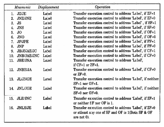
Last four instructions are utilized in the case of on signed binary number and decisions based operations, while all the remaining instructions may be utilized for unsigned binary operations.  The  terms  below  and  above  are usually  utilized for unsigned  numbers, while the terms greater and less are utilized for signed  numbers. A conditional jump instruction that does not examine status flags for condition testing, is following:

JCXZ 'Label' Transfer execution control to address 'Label', if register CX is equal to zero.

The conditional LOOP instructions are shown in following table along with their meanings. These instructions can be used for implement structures like REPEAT_UNTIL, DO_WHILE etc.

1192_cli.jpg

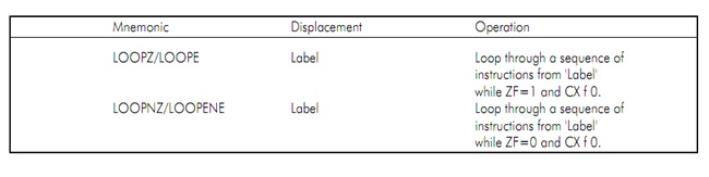
                                         Figure: Conditional loop instructions

The ideas regarding all these instructions will be clearer with the programming practice. This topic is intended at introducing these instructions to the readers. Of course, the examples are quoted wherever possible but the LOOP and the JUMP instructions need a sequence of instructions for explanations and will be emphasized.


Related Discussions:- Conditional branch instruction-microprocessor

Solotuon, using 8086 assembly language that interchange upper four bits to ...

using 8086 assembly language that interchange upper four bits to lower four bits. assume that data store in byte memory and it written back to same location. and assume the data as

LC-3 Program, Write an Lc-3 assembly language program to read in a sequence...

Write an Lc-3 assembly language program to read in a sequence of single-digit positive integers from the keyboard(one integer per line) until the sentinel value of 0 is reached and

Counters, #question. counters using 8051.

#question. counters using 8051.

Imul-arithmetic instruction-microprocessor, IMUL: Signed Multiplication: T...

IMUL: Signed Multiplication: This instruction multiplies a signed byte by a signed bit in source operand e in the register AL or signed word in source operand by signed word in th

Ddition, Write a program that performs the addition, subtraction, multiplic...

Write a program that performs the addition, subtraction, multiplications, division of the given operands. Perform BCD operation for addition and subtraction.

Prime finder - assembly program, Prime Finder - assembly program: Pro...

Prime Finder - assembly program: Problem:  Prime Finder   In this problem you will write a small program that tests whether a given integer is a prime number or not.  Let's

input and output, Description: LC3 allows input from keyboard and out...

Description: LC3 allows input from keyboard and output to display on the screen. This lab will exercise the input/output capability using LC-3 Assembly language. Procedure

English, given a sentence, find the number of times a particular character ...

given a sentence, find the number of times a particular character or word appear. the sentence is to be entered by the user

8279 keyword /display controller-microprocessor, 8279 Keyword /Display Cont...

8279 Keyword /Display Controller : Figure shows the structure of 8279 and its interface to the bus. Addressing is according to the table given below. CS        RD

Timing diagram of minimum mode, give the explaination of timing diagram min...

give the explaination of timing diagram minimum mode memory write cycle

Write Your Message!

Captcha
Free Assignment Quote

Assured A++ Grade

Get guaranteed satisfaction & time on delivery in every assignment order you paid with us! We ensure premium quality solution document along with free turntin report!

All rights reserved! Copyrights ©2019-2020 ExpertsMind IT Educational Pvt Ltd