Cam
This is a mechanical member that imparts motion to another member called follower.
Illustration:
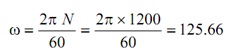
A cam is rotating at regular speed of 1200 rpm in the clockwise direction. This operates a roller following of 20 mm diameter having the data given as:
Minimum diameter of the cam = 60 mm
Maximum lift = 50 mm
Angle for rise with equivalent uniform acceleration and retardation = 120o
Angle for dwell after rise = 60o
Angle for return having equal uniform acceleration and retardation = 90o
Find out maximum acceleration & maximum velocity of the follower throughout rise and return.
Solution:
Maximum lift (L) = 50 mm, Angle for rise (θo) = 120o, Angle for return (θr) = 90o
The first step is to draw displacement diagram for the follower by supposing suitable scale.
(a) While follower axis passes through cam centre
(i) Draw a circle having radius equivalent to minimum radius of the cam to the scale that was decided for displacement diagram. Draw another circle having the similar centre having radius equal to (min. radius of cam + roller radius).
(ii) Show the sense of rotation & initial position of the roller.
(iii) Supposing cam stationary, follower is taken approximated it in the sense opposite to the sense of rotation of the cam. Beginning from initial location, mark angle for rise or ascent that means θo. After that mark for dwell period & then mark for return or descent angle say θr.
(iv) Divide angles θo & θr into similar number of equal pars like this is done in displacement diagram and in this case this is 8 equivalent parts. Draw radial lines.
(v) On extended radial lines transfer the equivalent displacement of the follower from displacement diagram above, the, prime circle (base circle radius + roller radius), that means 1 – 1′, 2 – 2′, etc.
(vi) Draw a series of arcs of radii equivalent to roller radius to defined roller positions from points 1′, 2′, 3′, 4′, etc.
(vii) Draw a smooth curve tangential to every arc of these to obtain the required cam profile.
Maximum velocity during rise =
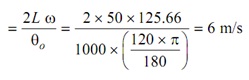
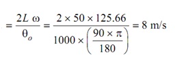
Maximum velocity during return =
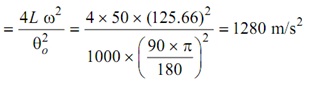
Maximum acceleration during rise =
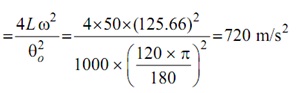
Acceleration during return =
(b) While follower axis is eccentric to the right
(i) Draw three concentric circles having radii equivalent to eccentricity, minimum cam radius and (minimum cam radius + roller radius).
(ii) Cam is supposed stationary, mark initial location of the follower that is tangential to the eccentricity circle, that means A – O′. The follower is taken about the cam in the sense opposite to the cam rotation. The follower axis shall always remain tangential to the eccentric circle.
(iii) Join O – O′. Having this line a zero angle line, mark angle for rise θo, dwell angle & angle for return θr.
(iv) Divide angle for rise θo & angle for return θr into similar number of equivalent parts like it is done in displacement diagram & in this case this is 8 equivalent parts and gets points, 1, 2, 3 . . . 17 on the prime circle.
(v) Draw tangents on the eccentricity circle from points 1, 2, 3, etc.
On the extended tangent lines, transfer the equivalent displacement of the follower from displacement diagram above prime circle that is 1 – 1′, 2 – 2′, etc. Repeat (e) & (f as denoted in past (a) of this instance to get the needed cam profile.