Calculate all the mass-normalised modal vectors, Mechanical Engineering

Assignment Help:

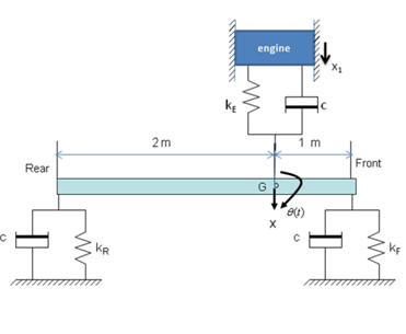
The body, suspension and engine mounting system of a vehicle may be idealised as a three degree of freedom system consisting of a bar of mass 1400 kg and the centre of mass at G, 1 m from the front and 2 m from the rear ends as shown in the Figure Q1. The suspension system consists of springs and dampers, the front suspension consists of a spring of stiffness of kF = 25 kN/m and damper of damping coefficient c and the rear with stiffness of kR = 20 kN/m and damping coefficient of c. The moment of inertia of the vehicle about point G is1200 kgm2. The engine and its mount is idealised as mass-spring-damper attached to the vehicle at G to isolate the engine vibration transmitted to the vehicle, the engine has a mass of 400 kg, the isolator has stiffness kE= 10 kN/m  and damping coefficient of c.

(a)          Draw the free body diagrams of the system and show that the equation of motion for the undamped system is given by:

518_equation1.png

(b)  Use eigen functions in MATLAB to calculate all the mass-normalised modal vectors and associated undamped natural frequencies. Hence sketch the modeshapes illustrating the dynamic behaviour of the system. Use hand calculations wherever possible to verify the results obtained from MATLAB.

(c)   If the damping due to the suspension and engine mount isolator are to be included in the model, modify the equation of motion given in part (a) to include the damping matrix, use the damping coefficient c.

(d)  The engine produces a sinusoidal excitation force of magnitude 150 N at frequency of 30 Hz, further excitation forces from the road are in the form of unit impulses applied to the front and rear ends of the vehicle, using Modal Analysis calculate the response of the system at the front suspension. using MATLAB plot the response in time domain. Assume a damping ratio of 0.1 for all modes.

(e)  Calculate one Frequency Response Function in Inertance form and plot it in the frequency range of interest using MATLAB.

Include all your MATLAB outputs and label them clearly. State all the necessary assumptions clearly. You may Export the MATLAB plots into word documents.
749_MATLAB.png


Related Discussions:- Calculate all the mass-normalised modal vectors

Spring, strain energy = m2l/2Ei

strain energy = m2l/2Ei

Explain construction and working of rope brake dynamometer, Explain constru...

Explain construction and working of Rope Brake Dynamometer? Determine Power also ?

#totto cycleitle.., for an otto cycle, compression ratio=8.5:1,air inlet=15...

for an otto cycle, compression ratio=8.5:1,air inlet=15degree celsius and pressure=101.3kpa, maximum cycle temperature= 1800degree celsius, what is temperature after compression,te

Wedge friction, WEDG E FRICTION: Explain how wedge is used for raisi...

WEDG E FRICTION: Explain how wedge is used for raising heavy loads. Also give principle of it. Sol.: Principle of wedge: A wedge is small piece of material having two

Vectors, Following sets of the three forces act on a body,. In which case r...

Following sets of the three forces act on a body,. In which case resultant cannot be zero? 1) 10N, 10N, 10N 2)10N, 10N, 20N 3)10N, 20N, 20N 4010N, 20N, 40N Ans)      In 4th

Newtons ring, a plano concave lens is used instead of plano convex lens in ...

a plano concave lens is used instead of plano convex lens in newtons ring

Typical joint designs used in electron beam welding, TYPICAL JOINT DESIGNS ...

TYPICAL JOINT DESIGNS THAT ARE USED IN ELECTRON BEAM WELDING Butt joint : Butt joint is the preferred joint as it involves only a small amount of machining prior to wel

Corrosion of bfw pump, Q. Show Corrosion of BFW Pump? BFW pumps are in ...

Q. Show Corrosion of BFW Pump? BFW pumps are in high-pressure high-temperature service and may be subject to cavitation and erosion-corrosion. Also overheating of these pumps i

Matlab program, write a matlab program to generate shear force diagram

write a matlab program to generate shear force diagram

Torque carried by the hollow shaft, Torque carried by the hollow shaft: ...

Torque carried by the hollow shaft: A hollow and a solid shaft of similar material have the same weight when the inner diameter of the hollow shaft is half its outer diameter.

Write Your Message!

Captcha
Free Assignment Quote

Assured A++ Grade

Get guaranteed satisfaction & time on delivery in every assignment order you paid with us! We ensure premium quality solution document along with free turntin report!

All rights reserved! Copyrights ©2019-2020 ExpertsMind IT Educational Pvt Ltd