Analyse the beam, Mechanical Engineering

Assignment Help:

Analyse the beam:

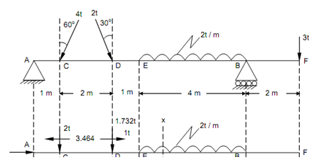
Analyse the beam illustrated in Figure and draw the SFD, BND & thrust diagram. Situated the point of contraflexure, if any.

1146_Analyse the beam.png

Figure

Solution

Vertical component of 4 kN at C, = 4 × cos 60o = 2 kN ( ↓ )

Horizontal component of 4 kN at C, = 4 × sin 60o = 3.464 kN ( ← )

Vertical component of 2 kN at D, = 2 × cos 30o = 1.732 kN ( ↓ )

Horizontal component of 2 kN at D, = 2 × sin 30o = 1 kN ( → )

Taking moment around A,

R B   × 8 - (3 × 10) - 2 × 4 × (4 + (4/2)) - (1.732 × 3) - (2 × 1) = 0

RB  = 10.6495 kN

RA  = 2 + 1.732 + (2 × 4) + 3 - RB  = 14.732 - 10.6495 = 4.0825 kN

Shear Force (beginning from the Left End A)

SF at A, FA  = + 4.0825 kN

SF just left of C, FC  = + 4.0825 kN

SF just right of C, FC  = + 4.0825 - 2 = + 2.0825 kN

SF just left of D, FD  = + 2.0825 kN

SF just right of D,  FD  = + 2.0825 - 1.732 = + 0.3505 kN

SF at E, FE  = + 0.3505 kN

SF just left of B, FB  = + 0.3505 - (2 × 4) = - 7.6495 kN

SF just right of B, FB  = - 7.6495 + 10.6495 = + 3 kN

SF just left of F, FF  = + 3 kN = load at the end F.

Bending Moment (beginning from the F)

BM at F,          MF   = 0

BM at B,  M B  = - (3 × 2) = - 6 kN-m

BM at E, M E  =+ (10.46 95 × 4) - (3 × 6) - ( 2 × 4 ×( 4/2))   =+ 8.599 kN-m

BM at D, BM at C,

M D  = + (4.0825 × 3) - (2 × 2) = + 8.2475 kN-m

M C  = + (4.0825 × 1) = + 4.0825 kN-m

 BM at A,        MA = 0

Maximum Bending Moment

Maximum bending moment shall occur at B and among B and E. Consider a section XX at a distance x from the end F.

Fx  = - 10.6495 + 3 + 2 ( x - 2)

For maximum bending moment, Fx must be equal to zero.

- 10.6495 + 3 + 2x - 4 = 0

x = 5.82475 m ≈ 5.825 m

BM at section XX,

∴          M x = + 10.6495 ( x - 2) - 3x - 2 ( x - 2) × (( x - 2)/2)

                   = 10.6495 ( x - 2) - 3x - ( x - 2)2

M max  = 10.6495 (5.825 - 2) - 3 (5.825) - (5.825 - 2)2

=+ 8.629 kN-m

Maximum positive bending moment = + 8.629 kN-m

Maximum negative bending moment = - 6 kN-m.

Point of Contraflexure

Equating the BM at section XX, to zero.

10.6495 ( x - 2) - 3x - ( x - 2)2  = 0

or         10.6495 x - 21.299 - 3x - x2  + 4 x - 4 = 0

or         x2  + 11.6495x - 25.299 = 0

or         x2  - 11.6495x + 25.299 = 0

Solving out by trial and error, we obtain x = 2.9 m.

Point of contraflexure is at a distance of 2.9 m from the end F.

Thrust Diagram

Horizontal reaction at A,

+ H A  + 3.464 - 1 = 0

+ H A  + 2.464 = 0

∴ H A  =- 2.464 kN

 ('-' denote that the reaction is towards right)

The portion AC is subjected to a compressive force of 2.464 kN. The part CD is subjected to a tensile force of 1 kN (that means3.464 - 2.464 = 1).


Related Discussions:- Analyse the beam

AUTOMOTIVE CONTROL, Ask DIFFERENTIAL AMPLFIER USED WITH THERMOCOUPLEquestio...

Ask DIFFERENTIAL AMPLFIER USED WITH THERMOCOUPLEquestion #Minimum 100 words accepted#

Electron beam welding(ebw)-basic principle, BASIC PRINCIPLE OF ELECTRON BEA...

BASIC PRINCIPLE OF ELECTRON BEAM WELDING(EBW)   Electron beam welding which utilises a heat source of electrons which are accelerated by an electric field to mextremely high

Calculate the density of the composite, Five kilograms of continuous boron ...

Five kilograms of continuous boron fibers are introduced in a unidirectional orientation into 8 kg of an aluminum matrix. Calculate a.  the density of the composite b.

QFD chart and engineering specifications, Deliverables: A QFD chart, sh...

Deliverables: A QFD chart, showing the relationships between the customer requirements and the engineering specifications. (Refer to the Ullman QFD chart posted on My

Determine the number of bolts required, The following specification is used...

The following specification is used for the design of a flanged coupling between two coaxial shafts: Speed: 650rpm Power transmitted: 550 kW Bolt Diameter: 12 mm Pit

Calculate the suitable diameter for a solid shaft, A shaft is hinghed by tw...

A shaft is hinghed by two bearings placed 1.0 m apart. A 600mm diameter pulley is mounted at a distance of 300 mm to the right of left hand bearing and this operates a pulley direc

Calculate the induction motor efficiency, Question: Characterisation te...

Question: Characterisation tests have been performed on a four pole, 415 V (line to line), three phase, star connected, 50Hz induction motor, with the following results:

Basic troubleshooting of motorcycle, Basic Troubleshooting of Motorcycle we...

Basic Troubleshooting of Motorcycle we have studied about the basic troubles in motorcycle operation and their solutions. It will help you in finding out the problem with the vehic

Determine the maximum torque - shaft, Determine the maximum torque - shaft:...

Determine the maximum torque - shaft: Determine the maximum torque that can be safely transmitted by a shaft of 400 mm diameter, if (a) the maximum allowable shear stress i

Cylinder head-basic components of engine , Cylinder Head: It is fitted at...

Cylinder Head: It is fitted at top of the cylinder block. It provides space for the arrangement of spark plug, combustion chamber, camshaft, cam chain, valves and intake and exha

Write Your Message!

Captcha
Free Assignment Quote

Assured A++ Grade

Get guaranteed satisfaction & time on delivery in every assignment order you paid with us! We ensure premium quality solution document along with free turntin report!

All rights reserved! Copyrights ©2019-2020 ExpertsMind IT Educational Pvt Ltd