Reference no: EM132239808
1. MATLAB simulation of a basic robotic arm
2. GUI which displays different actions the arm can perform
3. When a button is clicked, the arm performs the simulation
Dynamic simulation environment in MATLAB Simulink to show a basic robotic arm + 3 finger hand interacting with objects and performing two simulations.
This should be created with simple buttons on the GUI to control actions of the robotic arm.
The design of the robotic arm will be as follows:
Arm Design
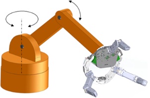
1 The design of the robotic arm will be a ‘articulated' style robot.
2 The arm design will be a ‘jointed arm robot' style, with a vertical column that swivels at the base (T-joint). A shoulder joint is at the top of the column (R-joint). Output link will be the joint for the robotic hand. See diagram for details.
3 The robotic hand will be 3-fingered with a palm-finger composed hybrid structure. See diagram for visual representation.
4 Size of the robotic arm within simulation will mimic average human arm measurements
5 Robotic arm and end effector will have the correct number of joints in order to fully function
For a visual representation of what the arm should look like. This is open to interpretation. If you feel like it should be designed differently please let me know. This design will be used for the kinematics model and the dynamic simulations:
Simulink GUI
1 GUI will include the following: 2 command buttons, 1 reset button, the robotic arm and the x,y,z numerical axis. See diagram for example.
2 The 3 command buttons will be:
1. Slice Veg
2. Stir Food
3. Reset
3 When button 1 or 2 is clicked, a further menu will pop up, asking for specific details about the command.
4 When the details of the command have been specified, the user will click ‘Confirm'. The robot will then perform the action
5 Once the action has finished, the reset button can be clicked to reset the simulation
Similar to this, but with the correct buttons and arm:
Dynamic Simulations
1 The 2 simulations need to show the robotic arm moving and interacting with objects to perform the required task.
2 Objects for the command will appear on the screen when the command is clicked, and disappear when 'Reset' button clicked.
3.1 Command 1: Slice Veg
The robot will pick up the knife object, and perform a cutting motion through the food object. The simulation does not need to show the food object in multiple pieces after being cut, just the motion of the knife going through it.
3.2 When the button ‘Slice Veg' is clicked, a menu will show which requires the user to enter details such as length, width and height of the object. Also, the distance between cuts will be specified. Put validation on the values + boundaries of a reasonable amount.
E.g. Length 500mm, Height 50mm, Width 50mm, Cuts 30mm.
3.3 Two objects which will be displayed. A knife, and the food object. See diagram for example of the object's images.
4.1 Command 2: Stir Food
The robot will pick up an object, imitating a wooden spoon. It will then perform circular motions around the Bowl object, imitating stirring of food, for the duration specified.
4.2 When the button ‘Stir Food' is clicked, a menu will show which requires the user to specify the bowl dimensions; diameter and depth. It will also ask for duration of stir. Put validation on the values + boundaries of a reasonable amount.
E.g. Diameter 300mm, Depth 200mm, Duration 30 seconds.
4.3 Two objects will be displayed. A wooden spoon object and a bowl object. See diagram for example of the object's images.
End to end run through of the simulation:
1. GUI opens with the robotic arm, 3 buttons and the axes
2. User clicks on a button e.g. Stir Food
3. Menu pops up asking the user to enter details. E.g. Diameter 300mm, Depth 200mm, Duration 30 seconds. User clicks confirm.
4. Objects for that function appear on the screen.
5. The robotic arm performs the simulation from start to finish.
6. Once finished, the reset button is clicked and the objects disappear, robotic arm back to starting position.
Note - all objects will need to be in 3D for the animation. These are just example photos.
Deliverables
You need to provide the MATLAB files along with a word processing document with the required diagrams, designs and explanations as requested. Don't expect a write up of the simulations, just some explanation on any difficult parts that will help to expand.
1 MATLAB Simulink Environment containing a robotic arm with a GUI that allows the user to click on relevant buttons and make the robotic arm perform basic simulations.
2 Complete code of the environment with comments - explanation of all code will also need to be provided.
3 Walkthrough of the environment - showing how to use different features and how to edit the robot or any functions if required.
5 System architecture that shows important info such as waypoint tracking details of object and robotic arm - refer to YouTube video 13:50 onwards. See examples below.
6 Forward and Inverse Kinematic designs that were created for the simulations - explanation required
7 Graphs showing the trajectories of the robotic arm during the simulations - with explanations.
8 Any designs that were created - will be helpful for me
9 Test cases for the simulation buttons, cover Normal values, Boundary values, Erroneous values
Include outcomes of the test cases
10 Explanation on how these simulations could be used within physical robots; steps required.
11 Full list of references
Attachment:- Requirements.rar