Reference no: EM132734278
Question 1:
Given a six-bar linkage with the link lengths Li = 0.1 m, 12 = 0. 04 m, L3 = 0. 12 m, and L4 = 0.O8 m, 15 = 0.05 m, L6 = 0.04 m, 17 = 0.07 m, find the values for Bs, 04, 05, 06, (1.1.3, Wi, tos, us, as, a4, as„. and a.s as shown in Figures 1, 2, and 3 for the open circuit of the linkage assuming 02 = 40*, w2= 25 rad/sec, and 0E2= 15 radfsec2.
The mass density is p=100DO0kern3, the link thickness T is 0.005 m, the joint shaft and hole radius (R1) is 0.005 m, the link radius (R2) is 0.01 m, and the two holes on the links are cut with a diameter d5cind d5 (15, and it;) away from the joints, respectively).
There is an external torque on the link 4 of 14 N•rn, applied at the centre of mass (44 on link 4, and at the same time an external force of F @&f acts on link 3, applied at point p and Ijaway from point A.
Taking gravity acceleration as 9.81miseca, find F12, F32, F43, F FM, F65, and F16 at the joints and the driving torque iii needed to maintain motion with the given angular velocity 4)2= 25 radisec and acceleration a2 = 15 radisee for this instantaneous position of the link (Figures 1 to 3).
1) Find the values of 83, 04, 85, 05, (63, W4, W5, W6,, a3, a4, as, and as
2) Find the accelerations of A4 (Akx„ A4v)(M/SeC2), ABA (AB.Ax, A64) (misec2), AB (AB:r.„ .ABy)(misec2), Ac Ate) (miseca), ADc (ADcx, Aped (m/sec), and
AD (Am, ADAMISeC2).
3) Find the centre of mass values I igg ig4 foal links 2,3, 4, 5, and 6.
4) Find the mass moment of inertia (kg•m2) about the centre of mass of links 2, 3, 4, 5, and 6.
5) Find the values of Ag2(Ag, Aga (Apx, Avv)„ Aga (Ag4g,, .Agadj Ag. (Agu,
Agsy), and Ars (AEG., Ate) of links 2, 3, 4, 5, and 6 (see Figure 3).
6) Find the force and moment equations for dynamic force analysis on links 2, 3, 4, 5, and 6, and cast the equations in the matrix form.
7) Find the values for Fu (Fm: and Flay), F32 (F3 and Fuld, F13 Rib: and Fi314,, F14 {F14): and F144, F54 {F5 and F540, F65 (F65 and F651), and F16 (Fier and Flsy) at the joints and the driving torque Ti2 needed to maintain motion with the given angular velocity and acceleration of uTz = 25 rad/sec and az =15 rod/ c2, respectively, for this instantaneous position of the link.
Regarding question 1, you have to write down the complete derivation of 1) to 7) rather than the final equation.

Figure 1: Dynamic force analysis of a six-bar linkage (front view)

Figure 2 Dynarnic force analysis of a sir-bar linkage (top view)
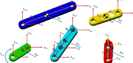
Figure 3 Dynamic force analysis of a six-bar linkage (free-body diagrams)
Question 2:
For the six-bar mechanism described in Problem 1, simulate the mechanism for the case in which the motion begins with a crank angular velocity of L12 = 25 radisec and a constant angular acceleration of ct2 =15 rad/sec'.
The matrix equation (matrix form in Problem 1) is solved using an rn-file function that will take all of the integrator outputs as input arguments (Figure 4).
1) Plot the values of 0 04, es, and O5for the first 2 seconds.
2) Plot the values of to2, L13, W4, Lo5, and cab for the first 2 seconds.
3) Plot the values of a2, ct3, a4, as, and of,5, for the first 2 seconds.
4) Plot the values of Ag2(AgZK, Ag2), Ag3 (Ag3x, Ag3.411 tkg4 (Avg, Agdy), Ag5 Ag5y), and Ag6(Ag6K, Ag6y) of links 2, 3, 4, 5, and 6 for the first 2 seconds.
5) Plot Fu (F123: and Ful), F32 (F323: and Fes,), F13 (F13x and Fd30, F11 Fla and Fuy), F51 F5 and F54y), FIBS (F65x. and F654. and F16 F16x. and Fi6y) at the
joints and the driving torque riz needed to maintain motion for the first 2 seconds.
6) Plot the coupler curve (plot x positions versus y positions) at the point of the centre of mass in Link 5.
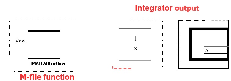
Figure 4 Simulink realisation of frill dynamics simulation of o six-bar mechanism
Question 3:
For the six-bar mechanism described in Problem 1, simulate the mechanism using Simscape for the case in which the motion begins with a crank angular velocity of toe = 25 rad/sec and a constant angular acceleration of az =15 radIrsec2.
1) Plot the values of 02, 03, leld, 65, and %for the first 2 seconds.
2) Plot the values of ii}20 (113, w4, w5, and us for the first 2 seconds.
3) the values of a2, as, aA., a5, and ao, for the first 2 seconds.
4) Plot the values of Ag2(Ag2y, Ag2y), Ag3 (4g3x, w F Ag4 Agado Ag5(Ag5x•
Ate), and Ag6(Ag6x, Ago.y) of links 2, 3, 4, 5, and 6 for the first 2 seconds.
5) Plot F12 (F123: and F120, F32 (F3234 and Faav), R13 Fay and Fey), F11 Fie and Flay), F54 (F54x and F540, F65 (F65x. and Foy), and F115 (F16:4. and Fioy) at the joints and the driving torque -1[1.2 needed to maintain motion for the first 2 seconds.
6) Plot the coupler curve (plot x positions versus y positions) at the point of the centre of mass in Link 5.
Question 4:
Compare the two simulation results obtained from questions 2 and 3.
1) Show the comparison of Aga (Aga. and Ag2y), Aga (Ag5x and Ag3y)„ Ag4 (Ag4 and Am), Ago. (Ag and Ape), and Ago (Ag6x. and Ag6y) on links 2, 3, 4,5, and 6 obtained from the two simulations (questions 2 and 3), and show the error graphs between the two simulations for the first 2 seconds.
2) Show the comparison of the force and torque components (Fla, Fuy, F32y, F4 F13 y, F F 14yo F54x, F 54y., F65x, Foy, Fla, F1, and ti) at all link joints obtained from the two simulation results (questions 2 and 3), and show the error graphs between the two simulations for the first 2 seconds.
Question 5:
The two simulation results are riot exactly the same. Express your opinion as to why that is, also describe what factors should be considered to improve the simulation results obtained from question 2 in comparison with the simulation results obtained from question 3.
Attachment:- equations for dynamic force.rar