Illustrate balanced delta-connected load, Electrical Engineering

Assignment Help:

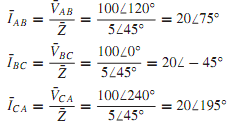
Next, let us consider the case of a balanced delta-connected load with impedance of 5 45° supplied by a three-phase, three-wire 100-V system, as shown in Figure (a). We shall determine the line currents and draw the corresponding phasor diagram. With the assumed positive phase sequence (A-B-C) and with ¯VBC as the reference phasor, the line-to-line voltages ¯VAB, ¯VBC, and ¯VCA are shown in Figure. The rms value of the line-to-line voltages is 100 V for our example. Choosing the positive directions of the line and phase currents as in Figure(a), we have

2166_Illustrate Balanced Delta-Connected Load.png

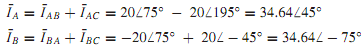
By the application of Kirchhoff's current law at each of the vertices of the delta-connected load, we obtain

858_Illustrate Balanced Delta-Connected Load1.png

2349_Illustrate Balanced Delta-Connected Load2.png

2162_Illustrate Balanced Delta-Connected Load3.png

The phasor diagram showing the line-to-line voltages, phase currents, and line currents is drawn in Figure(b). The load power factor is lagging, and is given by cos 45°. For a balanced delta-connected load, the phase voltages and the line-to-line voltages are equal in magnitude, and the line voltages are in phase with the corresponding phase voltages.

1261_Illustrate Balanced Delta-Connected Load4.png

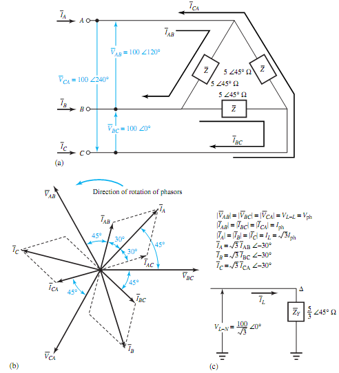
The line currents, in magnitude, are √3 times the phase currents, and the phase currents lead the corresponding line currents by 30°. The preceding example can also be solved by the one-line equivalent method for which the delta-connected load is replaced by its equivalent wye-connected load. The single-line equivalent circuit is shown in Figure(c). The details are left as an exercise for the student.


Related Discussions:- Illustrate balanced delta-connected load

Difference between div and idiv instructions, Mention how do the DIV & I...

Mention how do the DIV & IDIV instructions differ in their functionality DIV: Unsigned numbers division and IDIV: Signed number division.

Pneumatic circuit diagram, FIGURE shows a pneumatic circuit diagram used fo...

FIGURE shows a pneumatic circuit diagram used for air supply and exhaust in an automatic control system.  (a) Name all symbols (including pipelines) used in the system. (b) N

Find the inductor current and voltage, Q. The energy stored in a 2-µH induc...

Q. The energy stored in a 2-µH inductor is given by wL(t) = 9e-2t µJ for t ≥ 0. Find the inductor current and voltage at t = 1 s.

Show quantization error, Quantization Error Sampling followed by quanti...

Quantization Error Sampling followed by quantization is equivalent to quantization followed by sampling. Figure illustrates a message signal f (t) and its quantized version den

Industrial Automation, 1. Write the Boolean expression and draw the gate lo...

1. Write the Boolean expression and draw the gate logic diagram and typical PLC ladder logic diagram for a control system wherein a fan is to run only when all of the following con

Molecular chain, Molecular Chain (MIT, Princeton, Colorado) Consider a ...

Molecular Chain (MIT, Princeton, Colorado) Consider a one-dimensional chain consisting of N molecules which exist in two configurations, α, β, with corresponding energies  and

Calculate the ratio v/i for an ideal diode, Q. Assuming the diode to obey I...

Q. Assuming the diode to obey I = IS (e V/0.026 -1), calculate the ratio V/I for an ideal diode with I S = 10 -13 A for the applied voltages of -2,-0.5, 0.3, 0.5, 0.7, 1.0, and

Inductors, factors used to classify inductors

factors used to classify inductors

Mr, what is pole core and pole shoe in a dc machine

what is pole core and pole shoe in a dc machine

Write Your Message!

Captcha
Free Assignment Quote

Assured A++ Grade

Get guaranteed satisfaction & time on delivery in every assignment order you paid with us! We ensure premium quality solution document along with free turntin report!

All rights reserved! Copyrights ©2019-2020 ExpertsMind IT Educational Pvt Ltd