Expression for the normal and tangential stresses:
By sing Mohr's circle, derive expression for the normal and tangential stresses on a diagonal plane of material subjected to pure shear. Also state and explain the mohr's theorem for slope and deflection.
Sol.: Mohr circle is graphical method to find out stress system on any inclined plane through body.
It is circle drawn for compound stress system. The centre of circle has the coordinate 
and radius of circle is

by drawing mohr's circle of stress following 3 systems can be determined
(a) The shear stress, normal stress, and resultant stress on any plane.
(b) Principal stresses and principal planes.
(c) Maximum shearing stresses and the planes of them along with the associated normal stress.
Mohr's circle can be drawn for compound strain system.
1. Mohr's circle of stress with the reference to 2 mutually perpendicular principal stresses acting on the body considers both dike stresses.

Both the principal stresses can be considered as (a) Tensile and (b) Compressive.
Let us for tensile
That is;
σx> σy
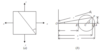
Steps:
l. Mark OA = Sx and OB = Sy, along x-axis (on positive side if tensile and negative side if compressive).
2. Draw circle with BA as diameter, called as mohr's circle of stress.
3. To obtain stress on any plane ¸ as shown in the figure given below measure angle ACP = 2¸ in anti clockwise direction.
4. The normal stress on the plane is Sn = OQ
Shear stress is τ = PQ
Resultant stress = σr = OP
And Angle POQ = ? is called as angle of obliquity.
2. Mohr's stress circle for a two dimensional compound stress condition shown in fig.
Let for a tensile
σx > σy
Steps:
l. Mark OA = σx and OB = σy along the x axis
[on positive side if tensile and negative side if compessive.]
2. Mark AC = τxy
and BD = τxy
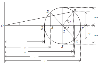
3. Join C and D that bisects AB at E centre of Mohr's circle.
4. With E as centre, EC or ED as radius draw the circle called as Mohr's circle of stress.
5. Point P and Q at which circle cuts S axis gives principal planes OP = σ1, and OQ = σ2 gives the 2 principal stresses.
6. ∠CEP = 2θ1 and ∠CEQ = 2θ2 can be measured in counter clockwise direction.
θ1 = (1/2) ∠CEP and θ1 = (1/2) ∠CEQ indicates principal planes.
7. ER = EC = τmax is the maximum shearing stress.
θ′1 = (1/2) ∠CER and θ′2
= (1/2) ∠CES
is measured anti-clockwise direction gives maximum shearing planes.
8. To obtain stress on any plane 'θ' measure ∠CEX = 2θ in anticlockwise direction.
Normal stress on the plane is,
σn = OY
Shear Stress, τ = XY
Resultant Stress is σr= OX
And
∠XOY = ? is known as angle of obliquity.