An engine repair workshop in County Durham has identified a need for a winch which is to lift complete engine assemblies from floor level up to workbench level to allow remedial work to be carried out at a more convenient and comfortable working height. The winch will be of traditional format and will broadly consist of motor which drive through a gearbox the cable drum around hook cable will be wound. The arrangement is shown in the block diagram in Fig 1 below.
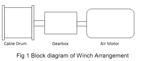
The motive power for the winch is to be an air motor which develops a maximum output power of 3.6kW at an output shaft speed of 2500 rev/min.
The repair workshop deals with a variety of different engines up to a maximum mass of 500kg which the winch must capable of lifting. To save money the owner of the workshop wants to use as many existing components as possible and has a identified a usable cable drum which has an effective diameter of 250mm which he wants used in the assembly.
All that remains to complete the winch is a design proposal for the gearbox which will provide the necessary increase in torque from the output shaft of the motor to the value at the cable drum to enable the cable to lift the maximum load.
SCOPE OF SUPPLY
You are required to prepare a design proposal for a reduction gearbox required to enable the winch to lift the maximum weight engine. All gears used in the gearbox must be accurately specified by manufacturer's name type and size and their selection backed by calculation. The proposed arrangement must fit within as small an envelope as possible. It is not a requirement for the design that the input and output shaft axes align but this would be an advantage as it should help to reduce space. To keep costs down only straight spur gears are to be used and these must be selected from those listed in Appendix 1.
DESIGN PORTFOLIO, ASSESSMENT & MARKING SCHEME
You are required to submit an individual design report which contains the following.
1) A design specification for the system. (Please note that this is a design specification and therefore needs to provide details of what it is you are required to design. It should include limitations imposed upon the design by the conditions described above. It must not be written as a product specification, i.e. a document which provides details of an existing product)
2) Calculations to determine the necessary torque required at the cable drum to lift maximum load and hence determine the overall gear ratio required for the gearbox.
3) From the list of available gears provided in Appendix 1 and taking account of the torque each gear must transmit, design a reduction gearbox to achieve the overall ratio required. Please note that this ratio does not need to be achieved in a single stage, it is acceptable to use any number of stages but costs must be kept to a minimum and the fewer the stages the less the cost will be. All gears used must be clearly listed and specified by part number, module, torque capacity and material type.
4) Prepare a schematic layout drawing (line drawing) of your gearbox showing all critical dimensions such as centre distances, gear diameters and widths and the shaft lengths and give the overall dimensions of the gearbox assembly.
5) Determine the gear forces set up and which act on each shaft, select an appropriate material (specified by a UK standard from the Roymech webpage) and calculate appropriate, standard sized shaft diameters for all shafts within your gearbox taking account of the bending moments set up by the gear forces and the torque that each shaft is required to transmit. (See combined Bending and Torsion notes.) NB the fewer shafts your gearbox has the easier this task will be!
6) Select an appropriate material (specified by a UK standard from the Roymech webpage) and determine the necessary size of all standard keys and keyways for each shaft gear interface in your gearbox, based on the torque that each shaft is required to transmit.