Uses of Zener Diode
Zener diodes are extensively used as voltage references and like shunt regulators to regulate the voltage across small circuits. While connected in parallel with a variable voltage source so that it is reverse biased, a Zener diode conducts while the voltage arrives at the diode's reverse breakdown voltage. From that point on, the comparatively low impedance of the diode holds the voltage across the diode at that value.
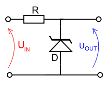
In this type of circuit, a typical voltage reference or regulator, an input voltage that is denoted by UIN, is regulated down to a stable output voltage that is denoted by UOUT. The intrinsic voltage drop of diode D is stable over a broad current range and holds UOUT comparatively constant even though the input voltage might fluctuate over a fairly wide range. Due to the low impedance of the diode while operated like this, Resistor R is employed to limit current through the circuit.
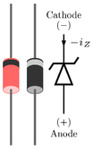
Figure: Zener diode shown with typical packages. Reverse current - iZ is shown.
In the case of this general reference, the current flowing in the diode is determined by using Ohms law and the known voltage drop across the resistor R. IDiode = (UIN - UOUT) / RΩ
The value of R has to be satisfies two conditions:
1. R must be enough small that the current via D keeps D in reverse breakdown. The value of this current is provided in the data sheet for D. For instance, the common BZX79C5V6 device, a 5.6 V 0.5 W Zener diode, has a suggested reverse current of 5 mA. If insufficient current exists by D, then UOUT will be not regulated, and less than the nominal breakdown voltage (this varies to voltage regulator tubes in which the output voltage will be higher as compared to the nominal and could rise as high as UIN). While measuring R, allowance must be made for any current via the external load, not displayed in this diagram, connected across UOUT.
2. R must be sufficiently large that the current via D does not destroy the device. If the current through D is ID, the breakdown voltage VB of it and the maximum power of it dissipation PMAX, then IDVB < PMAX.
A load might be located across the diode in this reference circuit, and as long as the zener stays in reverse breakdown, the diode will give a stable voltage source to the load.Shunt regulators are simple, but the needs that the ballast resistor be small enough to prevent excessive voltage drop throughout worst-case operation (low input voltage concurrent with high load current) tends to leave numerous current flowing in the diode much of the time, making for a quite wasteful regulator with high quiescent power dissipation, only appropriate for smaller loads.
Zener diodes in this type of configuration are frequently employed as stable references for much more advanced voltage regulator circuits.These devices are as well encountered, usually in series with a base-emitter junction, in transistor stages in which selective choice of a device centered around the avalanche or Zener point can be employed to introduce compensating temperature co-efficient balancing of the transistor PN junction. An instance of this type of use would be a DC error amplifier employed in a regulated power supply circuit feedback loop system.
Zener diodes are as well employed in surge protectors to limit transient voltage spikes. Other notable application of the zener diode is the make use of noise caused by its avalanche breakdown in a random number generator which never repeats.