Standard color-coded bands for evaluating resistance, Electrical Engineering

Assignment Help:

Standard Color-Coded Bands for Evaluating Resistance

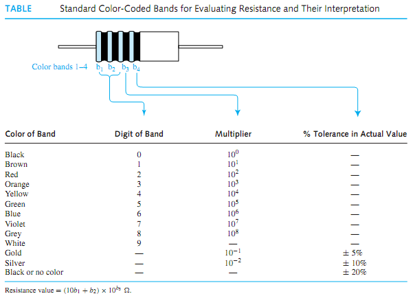
Practical resistors are manufactured in standard values, various resistance tolerances, several power ratings (as will be explained shortly), and in a number of different forms of construction. The three basic construction techniques are composition type, which uses carbon or graphite and is molded into a cylindrical shape, wire-wound type, in which a length of enamel-coated wire is wrapped around an insulating cylinder, and metal-film type, in which a thin layer of metal is vacuum deposited. Table illustrates the standard color-coded bands used for evaluating  resistance and their interpretation for the common carbon composition type. Sometimes a fifth band is also present to indicate reliability. Black is the least reliable color and orange is 1000 times more reliable than black.

For resistors ranging from 1 to 9.1 , the standard resistance values are listed in Table. Other available values can be obtained by multiplying the values shown in Table by factors
794_Standard Color-Coded Bands for Evaluating Resistance.png

of 10 ranging from 10  to about 22 × 106 . For example, 8.2 Ω ,82Ω , 820Ω , . . . , 820Ω k are standard available values.

The maximum allowable power dissipation or power rating is typically specified for commercial resistors. A common power rating for resistors used in electronic circuits is 1/4 W; other ratings such as 1/8, 1/2, 1, and 2 W are available with composition-type resistors, whereas larger ratings are also available with other types. Variable resistors, known as potentiometers, with a movable contact are commonly found in rotary or linear form. Wire-wound potentiometers may have higher power ratings up to 1000 W.


Related Discussions:- Standard color-coded bands for evaluating resistance

Weighted resistor and the r-2 r ladder d/a converters, Q. What is the basic...

Q. What is the basic difference between the weighted resistor and the R-2 R ladder D/A converters?

Explain the delay model, Explain the delay model based on logical effort of...

Explain the delay model based on logical effort often used in estimating delays in logic cells. Hence use the model to predict the delay of a 4-input NOR logic cell with a 3 times

Stack operation, Stack Operation Stack is a group of memory  locations...

Stack Operation Stack is a group of memory  locations which  are part of the  same read write memory  used for  storing  data  temporarily  during the execution of the  progra

Energy band diagram, Sketch the Fermi-Dirac distribution function, F(E), al...

Sketch the Fermi-Dirac distribution function, F(E), alongside the energy band diagram for an n-type semiconductor, indicating the position of the Fermi level, EF, and the donor lev

What do you mean by continuous signals, Q. What do you mean by Continuous s...

Q. What do you mean by Continuous signals? Continuous signals are described by time functionswhich are defined for all values of t (a continuous variable). Commercial broadcast

The relationship between cell and batteries, The relationship between cell ...

The relationship between cell and batteries  Generally, a cell delivers a certain voltage that is a function of what chemical reactions are taking place to generate the voltage

FSM(finite state machine, A sequential circuit has two inputs w1 and w2, an...

A sequential circuit has two inputs w1 and w2, and an output, z. Its function is to compare the input sequences on the two inputs. If w1=w2 during any four consecutive clock cycl

Self inductance , If a current is passed through a coil, it creates a flux ...

If a current is passed through a coil, it creates a flux within the coil. Any attempt to change this flux will create a back emf that acts to oppose the change.   Consider again

Find the net force experienced by a positive charge q, Q Two charges of equ...

Q Two charges of equalmagnitude 5µC but opposite sign are separated by a distance of 10 m. Find the net force experienced by a positive charge q = 2 µC that is placed midway betwee

Sr flip-flop, SR FLIP-FLOP (SRFF) The symbol for the SRFF is shown in F...

SR FLIP-FLOP (SRFF) The symbol for the SRFF is shown in Figure (a), in which S stands for "set," R stands for "reset" on the input side, and there are two outputs, the normal o

Write Your Message!

Captcha
Free Assignment Quote

Assured A++ Grade

Get guaranteed satisfaction & time on delivery in every assignment order you paid with us! We ensure premium quality solution document along with free turntin report!

All rights reserved! Copyrights ©2019-2020 ExpertsMind IT Educational Pvt Ltd