Pitch control unit (pcu) operation:
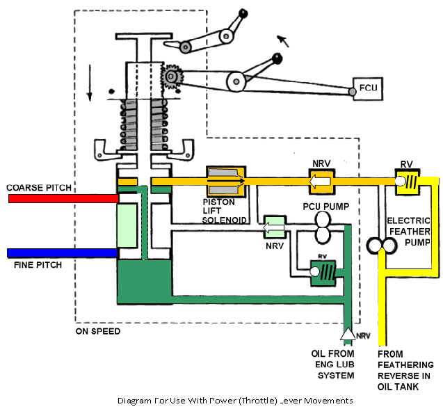
The action of the Governor bob weights, due to the varying RPM of the engine, is to raise or lower an internal piston to cover or open fluid pressure channels to move the propeller blades to the appropriate positions. There are three main conditions, ‘On Speed', ‘Under Speed', and ‘Over Speed'.
'ON SPEED' CONDITION
The speeder spring setting balances the centrifugal force acting through the governor weights.
The engine RPM is equal to that selected by the power lever.
The control valve is in a neutral position hydraulically locking the pitch change piston.
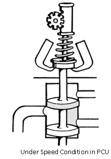
UNDER SPEED
Speeder spring load is greater than the force of the governor weights the valve is pushed down. Propeller blades move to a finer pitch to increase RPM.
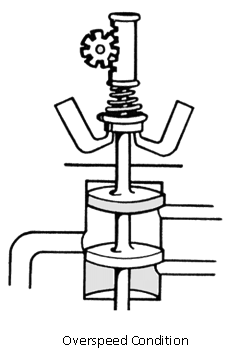
OVER SPEED
Centrifugal force of the governor weights overcomes the speeder spring load, the control valve moves up. Propeller blades move to a coarser pitch to decrease RPM.
RPM INCREASE SELECTED
Using the diagram at Fig Opposite follow the sequence of events outlined below.
Power lever moved.
Speeder spring load increased.
Control valve moves down.
Pressure oil directed to fine pitch line.
Return oil from coarse pitch line goes to pump inlet.
Blade angle changes to a finer pitch.
RPM increases as the load on the propeller reduces.
Governor weights fly outwards to lift the control valve as the RPM increases due to pitch change and increased power.
Control valve is moved to the 'on speed' position when speeder spring and governor weight forces balance.
The throttle / power lever is connected to the fuel control unit and the propeller control unit as shown in the diagram, increase the throttle, movement and you will increase the fuel flow. From the graph you will see this as a straight line linear increase, but the RPM and blade angle increases are not proportional.
To understand this we must first understand the anomalies of the Gas Turbine at low RPM's ( GI). As there is very little power available to drive the propeller any increase in propeller load (blade angle) will result in a resistance to rotation (torque), engine RPM will reduce and so will mass airflow.
The fuel control system is scheduling the fuel flow for normal ground idle (GI), which is no longer being obtained. This represents an over-fuelling condition and serious over-heating will occur. This problem exists anywhere over the idling RPM range, ground idle (GI) to flight idle (FI).
To overcome this, propeller control unit (PCU's) are designed with 'dead movement' see P.C.U. diagram. With reference to this diagram and the graph at Fig the following paragraphs explain the power (throttle) lever movements.