Engine controls:
Engine controls are very similar to flying controls, and the same types of equipment are used, such as rods, bellcranks and cables. Most control systems use either one or two systems to control the engine.
In a two path system the high pressure cock is controlled separately from the throttle, in a single path system they are combined.
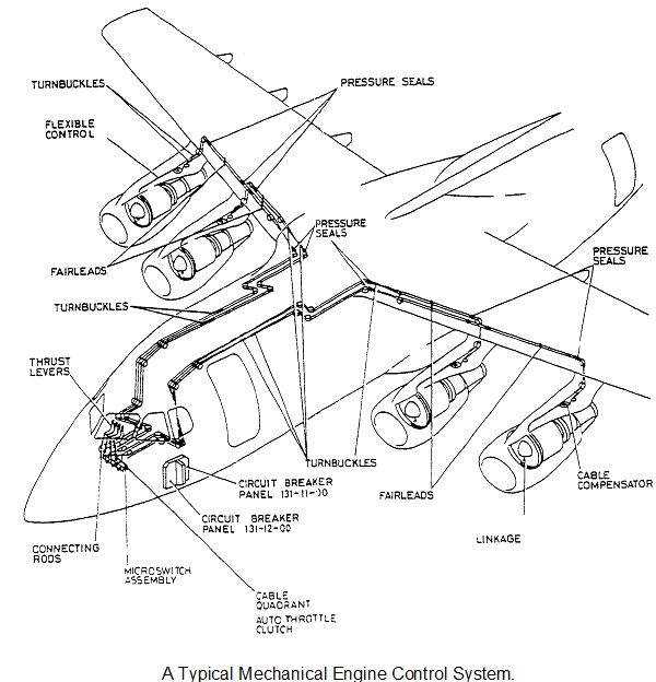
TURBOFAN ENGINE CONTROLS.
Figure shows a typical mechanical control system for a turbofan powered aircraft. It uses a single path system to transmit power requirements to the engine. The thrust lever is connected to a rod that transmits the movement down below floor level to a quadrant. The quadrant outputs to two cables which initially run under the floor of the flightdeck and then along the roof of the passenger cabin. They then pass through pressure seals and along the leading edge of the wing before dropping down to a cable compensator in the top of the pylon. The output from the compensator quadrant is a teleflex push/pull cable. This teleflex cable passes down into the engine nacelle to a torque shaft mounted on the nose cowl assembly. The output from the torque shaft moves a rod which provides the input to the fuel control unit. The teleflex cable has a disconnect break mechanism in it to facilitate engine changes.
To allow autothrottle functions the quadrants below the thrust levers can be moved by an actuator which drive all four levers via clutches.
TURBOPROP ENGINE CONTROLS
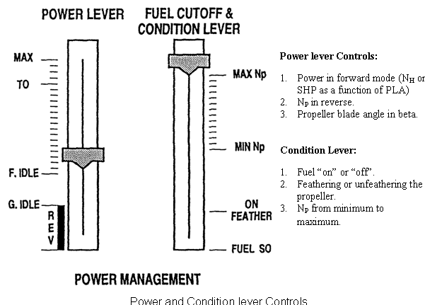
Figure shows a typical mechanical control system for a turboprop engine. It uses a double path system to transmit power requirements to the power unit,i.e. the power lever controls engine power in the normal operating modes and both power and propeller blade angle in the beta mode. A condition lever controls propeller blade angles in the normal mode, and also controls the feathering of the propeller and the HP shutoff cock.
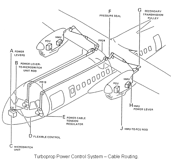
Power Controls.
The power lever controls, via the Hydromechanical Control Unit (HMU)the full flow from "MAX" (maximum power) to "REV" (reverse). Power lever movement is transmitted to the HMU via a series of push/pull rods and cables. A control rod between the HMU and the Propeller Control Unit (PCU) enables control of propeller blade angle in beta mode.
Propeller/HP Shutoff Cock Control
The "Condition Lever" controls via the PCU propeller speed from, "Min NP" (minimum propeller speed) to "Max NP" (maximum propeller speed). Condition lever movement is transmitted via a series of push/pull rods and cables, similar to the power lever controls. A second control rod between the PCU and HMU enables control of the HP fuel shutoff cock within the HMU by the condition lever. The condition lever also controls feathering of the propeller