Phase lead controller design and digital implementation, Electrical Engineering

Assignment Help:

The arm of a hydraulic robot is controlled as shown in the block diagram below:

501_Phase Lead Controller Design and Digital Implementation.png

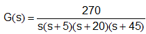
The arm dynamics are represented by:

1774_Phase Lead Controller Design and Digital Implementation1.png

Dynamic specification for the arm requires:

  1. Percentage overshoot for a step input < 20%
  2. Rise time < 1.2 seconds
  3. Velocity constant, Kv ³ 10

Part 1: Phase Lead Controller Design

1. Design a suitable phase-lead controller. You should explain in detail how your design has been developed.  Your solution should include Bode plots constructed both manually and using an appropriate package such as MATLAB or Scilab.

2. Using the design rules in the Control Engineering Data Sheets, obtain the TF of the "equivalent" 2nd order TF (including controller).

3. Compare the unit step responses of the equivalent 2nd order TF and the actual closed loop system, and comment on the accuracy of the equivalent.

Part 2: Digital Controller Implementation

1. Using the phase lead controller transfer function obtained above as a prototype, design a digital controller using the Bilinear Transform or any other method of your choice.

2.  Select a suitable sampling increment, T, given the following constraints:

a. the minimum value for T is, T= 1mS

b. the value of T should be as large as possible, but must provide a unit step response that is within a 5% error band around the unit step response obtained from the 'ideal' closed loop system designed in Part 1.

3. Compare the performance of the digital controlled system with the analogue controlled system obtained in Part 1 (this should include consideration of both time domain and frequency domain responses).


Related Discussions:- Phase lead controller design and digital implementation

Switching characteristics, Switching Characteristics The switching  cha...

Switching Characteristics The switching  characteristic  of an IGBT  during  turn on and turn off time all  shown  in the sum of delay time  and rise time gives  the total  tur

Explain amplitude-shift keying, Q. Explain Amplitude-shift keying? A ca...

Q. Explain Amplitude-shift keying? A carrier's amplitude is keyed between two levels (binary 1 and 0) in binary ASK. Figure shows the functions of a coherent ASK communication

Find the total input power, Q. A 230-Vdc shuntmotor delivers 30 hp at the s...

Q. A 230-Vdc shuntmotor delivers 30 hp at the shaft at 1120 r/min. If the motor has an efficiency of 87% at this load, find: (a) The total input power. (b) The line current.

Compute the area of each plate for parallel-plate capacitor, Q. For a paral...

Q. For a parallel-plate capacitor with plates of area A m 2 and separation d m in air, the capacitance in farads may be computed from the approximate relation Compute the

Show the dot convention, Q. For the coupled coils shown in Figure, a dot ha...

Q. For the coupled coils shown in Figure, a dot has been arbitrarily assigned to a terminal as indicated. Following the dot convention presented in the text, place the other dot in

Multiplexer, design a 32:1 multiplexer using two 16:1 multiplexer

design a 32:1 multiplexer using two 16:1 multiplexer

Feedback amplifier, #I want to get lecture notes on Electronic device.and c...

#I want to get lecture notes on Electronic device.and circuits .

Electronics, Figure 1(a) shows a simple one-stage MOSFET amplifier. The inp...

Figure 1(a) shows a simple one-stage MOSFET amplifier. The input-output relationship is graphed in Figure 1(b), where the solid curve indicates operation in the saturated region an

Write Your Message!

Captcha
Free Assignment Quote

Assured A++ Grade

Get guaranteed satisfaction & time on delivery in every assignment order you paid with us! We ensure premium quality solution document along with free turntin report!

All rights reserved! Copyrights ©2019-2020 ExpertsMind IT Educational Pvt Ltd