Low frequency loop impedance:
Low frequency loop impedance testing is a useful method complementary to DC bonding testing. A visual inspection of cable bundle shields, complemented by a low frequency loop impedance test, gives good confidence in the integrity of the shielding provisions.
Low frequency loop impedance testing is a method developed to check that adequate bonding exists between over braid (conduit) shields and structure. To achieve the shielding performance required, it is often necessary that both ends of a cable bundle shield be bonded to aircraft structure. In such cases, it is hard to check bonding integrity by the standard DC bonding test method. If the bond between shield and structure at one end is degraded while the other one is still good, there is little chance to find this defect by performing DC bonding measurements. The remaining bond still ensures a low resistance to ground but the current loop through the shield is interrupted, causing degradation of shielding performance. The fault can easily be detected by performing a low frequency loop impedance test.
The test set-up requires simple test equipment, refer to Figure. A current of about 1 kHz is fed into the conduit under test while measuring the voltage necessary to drive that current. Other versions of the loop impedance test arrangement use different frequencies (200 Hz is typical), and provide the resistive and reactive parts of the loop impedance.
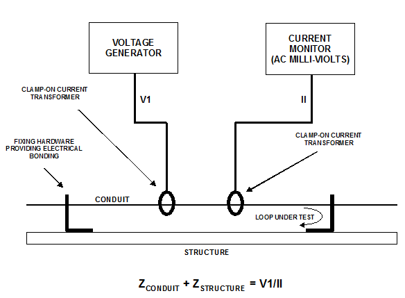
The test equipment consists of a generator operating at 1 kHz feeding an injection probe and a current monitoring probe, connected to an AC millivoltmeter. A voltmeter connected to the generator enables the voltage necessary to drive the current to be measured. 1 kHz is a high enough frequency to drive the injection and the monitoring probes and is also enough to avoid specific RF effects, like non-uniform current distribution along the loop under test.
If, in practice, the current is set to 1A, the voltage figure, when expressed in millivolts, gives the loop impedance in milliohms directly. The loop impedance is normally in the range 1-100 milliohms. In this range, accurate results can easily be achieved.
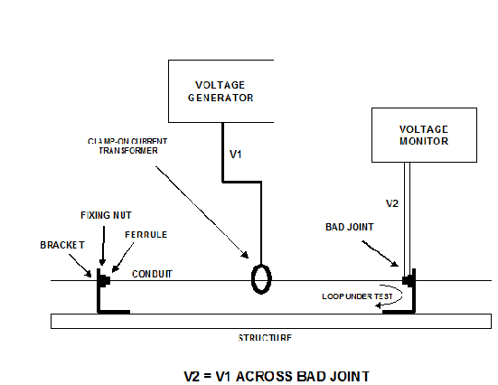
If too high loop impedance is found, the joint determining the problem has to be identified. This can be performed by measuring the voltage drop across each joint. The joint with the high voltage drop across it is the defective one, refer to Figure.
As there is no need for a wide band swept RF generator, the test equipment can be quite simple and easy to handle. Hand held battery powered test equipment, especially designed for production monitoring and routine maintenance, is available on the market.