Illustrate theories in planning a machining sequence, Mechanical Engineering

Assignment Help:

Illustrate theories in planning a machining sequence

A component requires several machining operations to bring it to a final shape. The sequence of these operations are arranged optimally to attain maximum possible production. The following condensed example is presented in order to illustrate basic theories and reasoning followed by process engineer in planning a machining sequence. This example does not consider auxiliary and supporting operations; rather only the major process operations.

The operation sequence for the given pinion blank shown in Figure 11 is given below.

2151_Illustrate theories in planning a machining sequence.png

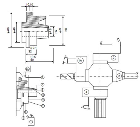
                         Figure 11: Pinion Blank

Facing of the surfaces 4 and 7 must be done first using two carbide tipped facing tools fixed on front slide of the turret lathe. The process may take 175 seconds per piece for full cycle of operation.

Operation 02

This operation can be done simultaneously with operation 5 by using a combination of tools like bore, drill φ17 HSS and carbide turning tool fixed in position 1 A of square turret. The operations included are

 (a)       Rough boring,

 (b)       Semi-finish turning of diameter 3, and

 (c)       Semi-finish facing of face 2.

Operation 03

The chamfers 6 and 5 must be finished using two chamfering tools fixed in position 2 of the turret.

Operation 04

Finishing of chamfer 1 may also be performed simultaneously with operation 10 by providing a chamfering tool on the rear slide.

Operation 05

Semi-finish boring of hole 8 may be done using a carbide tool fixed in boring bar at position 3 of turret.

Operation 06

Hole 8 must be reamed and surfaces 2 and 3 be finish turned by a combination of tools fixed at position 4 of turret by using HSS reamer 18K6 and carbide tipped turning tool.


Related Discussions:- Illustrate theories in planning a machining sequence

Electron beam welding-working chamber, Working Chamber of EBW Th...

Working Chamber of EBW The chamber is usually rectangular in shape and has heavy windows to permit viewing the work. Both high voltage machines and low voltage machines

Explain the open system - thermodynamic, Explain the Open system - Thermody...

Explain the Open system - Thermodynamic The system that can exchange both of the mass and energy that is Heat and work with its surrounding, the mass in the system may not be c

Explain the semi universal drilling machine, Explain the semi universal dri...

Explain the semi universal drilling machine The semi universal drilling machine this machines, in addition to the above three basic movements, carry provision for swinging of

Manual engineering drawing , Manual Engineering Drawing: The physical o...

Manual Engineering Drawing: The physical object is to be drawn (Do not take photographs of the object or use it as a template that you trace with) in class as an isometric dra

Simple rules-priority rules-conventional priority rules, Simple Rules F...

Simple Rules FIFO (first in first out) PN j = t aj SPT (shortest processing time) PN j = o j ODD (earliest operation due dates) PN j = t dj EDD (earliest job due

Force exerted by jet on an fixed vertical plate, Show that the force exerte...

Show that the force exerted by jet of water on a fixed semi-circular plate in the direction of jet when the jet strikes at the centre of the semi-circular plate is two times the fo

What do you mean by extrusion, Q. What do you mean by extrusion? • Ex...

Q. What do you mean by extrusion? • Extrusion is a process used to create objects of a fixed cross-sectional profile. A material is pushed or drawn through a die of the desir

Ultrasonic welding, ULTRASONIC WELDING This is a solid state welding p...

ULTRASONIC WELDING This is a solid state welding process for joining similar or dissimilar metals by application of high frequency vibratory energy to work pieces held togethe

System of loads - beam, System of loads -  Beam: Build the SFD & BMD ...

System of loads -  Beam: Build the SFD & BMD for 10 m span simply supported beam subjected to a system of loads as illustrated in Figure . Figure Taking moment a

Write Your Message!

Captcha
Free Assignment Quote

Assured A++ Grade

Get guaranteed satisfaction & time on delivery in every assignment order you paid with us! We ensure premium quality solution document along with free turntin report!

All rights reserved! Copyrights ©2019-2020 ExpertsMind IT Educational Pvt Ltd