Illustrate output-rate control, Electrical Engineering

Assignment Help:

Q. Illustrate Output-rate control?

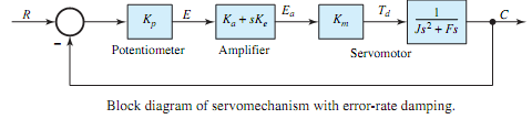
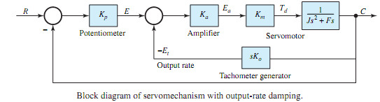
A system is said to have output-rate damping when the generation of the output quantity in some way ismade to depend upon the rate atwhich the controlled variable is varying.Output-rate control often involves the creation of an auxiliary loop, making the system multiloop. For the system of Figure, output-rate damping can be obtained by means of a tachometer generator, driven from the servomotor shaft. The complete block diagram of the servomechanism with output-rate damping is depicted in Figure, where Ko is the output-rate gain factor (V·s/rad) and the output-rate signal is given by Ko(dc/dt). By applying the feedback relationship of Equation to the minor (inner) loop, one gets

445_Illustrate Output-rate control.png

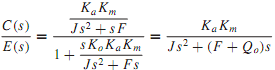
where Qo = KoKaKm is known as the loop output-rate gain factor. Figure may then be simplified. The closed-loop transfer function for the complete system is then given by

1215_Illustrate Output-rate control1.png

725_Illustrate Output-rate control2.png

243_Illustrate Output-rate control3.png

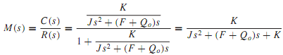
where K = KpKaKm is known as the loop proportional gain factor, as stated earlier.

The manner in which output-rate damping effects in controlling the transient response are most easily demonstrated is by assuming a step input applied to the system. The output-rate signal appears in opposition to the proportional signal, thereby removing the tendency for an excessively oscillatory response.With error-rate damping and output-rate damping, the damping ratio can be seen to be

412_Illustrate Output-rate control4.png

where Q = Qe or Qo, in which a term is added to the numerator, while the natural frequency is unchanged (as given by ωn = √K/J ). The damping ratio can then be adjusted independently through Qe or Qo, while K can be used to meet accuracy requirements.


Related Discussions:- Illustrate output-rate control

Fault analysis, The one line diagram of a simple three phase power system i...

The one line diagram of a simple three phase power system is shown in figure below. Each generator is represented by an emf behind the transient reactance. All impedances are expre

Explain standby mode of operation in spc organization, Q. Explain Standby m...

Q. Explain Standby mode of operation in SPC organization? Standby mode of operation is the simplest of dual processor configuration operations. Generally one processor is activ

A Capacitor-Fed, A Capacitor-Fed, Voltage-Step-Down, Single-Phase, Non-Isol...

A Capacitor-Fed, Voltage-Step-Down, Single-Phase, Non-Isolated Rectifier

FET operation, ON output plot of a JFET n-channel transistor if ID is close...

ON output plot of a JFET n-channel transistor if ID is close to IDSS does the value of VGS close to VP?

Provide definition of signals, Provide Definition of Signals A continuo...

Provide Definition of Signals A continuous-time signal x(t) is a signal that is a function of real number t. For a discrete-time signal x[n], it is a method of discrete time in

What is key bouncing, What is Key bouncing? Mechanical switches are us...

What is Key bouncing? Mechanical switches are used as keys in lots of the keyboards. When a key is pressed the contact bounce back and forth and settle down only after a littl

Electrostatic sprayer, I would like to know the materials needed for electr...

I would like to know the materials needed for electrostatic sprayer.

Find the voltage at the load terminal, Q. Two three-phase generators are su...

Q. Two three-phase generators are supplying to a common balanced three-phase load of 30 kW at 0.8 power factor lagging. The per-phase impedance of the lines connecting the generato

Write Your Message!

Captcha
Free Assignment Quote

Assured A++ Grade

Get guaranteed satisfaction & time on delivery in every assignment order you paid with us! We ensure premium quality solution document along with free turntin report!

All rights reserved! Copyrights ©2019-2020 ExpertsMind IT Educational Pvt Ltd