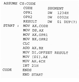
How to write an assembly program
The initial step in writing an assembly language program is to identify and study the problem. After studying the problem, choose the logical modules need for the program. From the statement of the program one can guess that some data can be needed for the program or the result of the program that is to be stored in the memory. Therefore the program will required a logical space called DATA segment. Always CODE segment is a part of a program containing the real instruction sequence to be executed. If the stack facility is used in the program, it will need the STACK segment. EXTRA segment can be used as an additional destination data segment. Make a note of that the use of all these logical segments is not necessary except for the CODE segment. Some programs may need CODE and DATA segments, while the others may also contain EXTRA and STACK. For instance, Program first requires only DATA and CODE segment.
The first line of the program is 'ASSUME' directive declares that the label CODE is to be used as a logical name for CODE segment and the label DATA is to be for DATA segment. These labels CODE and DATA are kept by MASM for these purposes only.
They should not be used as general labels. Once this statement is written in this program, CODE refers to the code segment and DATA refers to the data segment throughout the program If you desire to change it in a program you will have to write another ASSUME statement in the program.
The second statement DATA SEGMENT marks the beginning of a logical data space DATA Inside DATA segment, OPRI is the first operand. The directive DW describes OPRI as a word operand of value 1234H and OPR2 as a word operand of value 0002H. The third DW directive reserves OIH words of memory for storing purpose of the result of the program and leaves it undefined due to the directive DUP (?). The statement DATA ENDS marks the termination of the DATA segment. Therefore the logical space DATA contains OPRI and OPR2 and also the RESULT. These labels OPRI, OPR2 and RESULT will be allotted physical memory locations whenever the logical SEGMENT DATA is allocated memory or loaded in the memory of a computer as described in the earlier topic of relocation. Assembler calculates that the above data segment needs 6 bytes, for example 2 bytes each for RESULT, OPRI & OPR2.
The code segment in the above program begins with the statement CODE SEGMENT. The code segment as already described is a logical segment space having the instructions. The label STARTS marks the starting point of the execution sequence. The ASSUME statement only informs the assembler that label
CODE is used for the code segment and DATA label is used for the DATA segment. It does not in fact put the address corresponding to CODE in code segment register (CS) and address corresponding to DATA in the data segment register (DS). This process of putting the actual segment address values into the equivalent segment registers is called as segment register initialization. A programmer has to perform these initializations for DS, SS and ES by using instructions, whereas the CS automatically initialized by the loader at the time of loading the EXE file into the memory for definite execution. The first two instructions in the program are for data segment initialization. Note that, no segment register in 8086 may be loaded with instant segment address value, rather then the address value should be first loaded into any one general purpose registers and then the contents of the general purpose register can be transferred to any segment registers as DS, ES and SS. Also one should note that CS can't be loaded at all. Its contents may be changed by using a long jump instruction, an interrupt instruction or a call instruction. For the each of the segments register ES, DS and SS, the programmer will have to carry out initialization if they are used in the program, whilst CS is automatically initialized by the loader program at the time of loading and execution. Then the 2 instructions move the 2 operands OPRI and OPR2 respectively in register AX and BX. Carry is cleared before addition operation (optional in this program). The ADD instruction will add BX register into AX register and store the result in AX register. The instruction which is used to store the result in RESULT uses different addressing mode than that used for taking OPRI into register AX. The indexed addressing mode is used to store the result of addition in memory locations labeled RESULT. Instruction MOVDI, OFFSET RESULT stores the offset of the label RESULT into register Dl. Next instruction stores the result available in register AX into the address pointed to by Dl, for example address of the RESULT. A lot has been already described about the function calls under INT 21H. Function value 4CH is for returning to the DOS prompt. If instead of these 1 writes HLT instruction there will not be any difference in program execution except that the computer will be hang as the processor goes to HLT state, and the user will not be able to check the result. In that type of case, for further operation, one will have to reset the computer and boot it again. To ignore this resetting of the computer each time you run the program and enable one to examine the result, it is better to use the function call 4CH at the end of every program so that after executing the whole program, the computer returns back to DOS prompt. The statement CODE ENDS marks the end point of the CODE segment. Statement END START marks the end of the procedure that begun with the label START. At the end of the each file, the END statement is a necessary.
Assemble the above written program by using MASM after entering it into the computer by using the process explained past. Once you get the EXE file as the output of the LINK program, your listing is prepared for execution. The above Program is prepared in the form of EXE file with the name KMB.EXE in the directory. Next, it may be executed with the command line as given below.
C> KMB