Explain the three-line cable residential wiring, Electrical Engineering

Assignment Help:

Q. Explain the three-line cable Residential wiring?

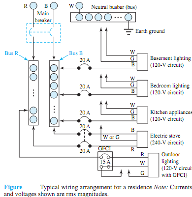
The three-line cable coming out of the secondaries of the distribution transformer on the utility pole passes through the electric meter that measures energy consumption in kilowatt-hours and terminates at the main panel. Figure 4.4.2 shows a typical wiring arrangement for a residence. At the main panel, circuit breakers serve the joint role of disconnecting switches and overcurrent protection; the neutral is connected to a busbar (bus) and in turn to the local earth ground; the hot lines are connected to individual circuits for lighting and appliances, as illustrated in Figure.

The circuit breaker labeled GFCI (ground-fault circuit interruption), used for safety primarily with outdoor circuits and in bathrooms, has additional features that will be described later. Note that every outgoing "hot" wire must be connected to a circuit breaker, whereas every neutral wire and ground wire must be tied directly to earth ground at the neutral busbar.

Today most homes have three-wire connections to their outlets, one of which is shown in Figure. The need for both ground and neutral connections needs to be explained, since the ground conductormay appear to be redundant, playing no role in the actual operation of a load that might be connected to the receptacle. From the viewpoint of safety, the ground connection is used to connect the metallic chassis of the appliance to earth ground. Without the ground conductor connected to the metal case of the appliance, as shown in Figure(a), the appliance chassis could be at any potentialwith respect to ground, possibly even at the "hot"wire's potential if a part of the "hot" wire were to lose some insulation and come in contact with the inside of the chassis.

An unintended connectionmay occur because of the corrosion of insulation or a loosemechanical connection. Poorly grounded appliances can thus be a significant hazard by providing a path to ground through the body of a person touching the chassis with a hand. An undersized ground loop current limited by the body resistance may flow directly through the body to ground and could be quite harmful. Typically, the circuit breaker would not operate under such circumstances.
422_Explain the three-line cable Residential wiring.png


Related Discussions:- Explain the three-line cable residential wiring

\, Refer to Figure 100. Assume MKS units. Given: R1= 4, R2=14, R3= 9, I4...

Refer to Figure 100. Assume MKS units. Given: R1= 4, R2=14, R3= 9, I4= 8, I5= 7. Determine: Ieq, Req, and V3.

What do you mean by ruled surface, a) Define the surface of revolution? ...

a) Define the surface of revolution? b) What do you mean by ruled surface?

Calculate armature voltage, Question: A DC, separately excited motor is...

Question: A DC, separately excited motor is supplied from a 240-V source. When the motor is unloaded, it draws 1A of current from the source. When the motor is loaded, it draws

Problem on pulse code modulation, (a) "Pulse Code Modulation (PCM), as used...

(a) "Pulse Code Modulation (PCM), as used in telephony, samples a signal at 8 kHz using 256 quantization levels". i. Outline how this scheme works with the help of sketches and,

Explain extrinsic semiconductor, Explain Extrinsic Semiconductor. Extr...

Explain Extrinsic Semiconductor. Extrinsic Semiconductor: An intrinsic semiconductor is able to conduct some current even at room temperature but as this is not helpful for t

Find the diameter of a circular waveguide, Q Find the diameter of a circula...

Q Find the diameter of a circular waveguide that will have a lower cutoff frequency of 10 GHz and also specify its largest usable frequency.

Control systems design, You are to choose a particular application, model a...

You are to choose a particular application, model and simulate it using MATLAB and or SIMULINK. 1. Modelling 2. Testing and verification of the model 3. Demonstration o

Equipment parameter data, Equipment parameter data: The schematic diag...

Equipment parameter data: The schematic diagrams for existing substations have to be prepared along with information of power transformer rating and numbers, impedance values,

Show that the effective inductance of the two coils, Q. The self-inductance...

Q. The self-inductances of two coupled coils are L 11 and L 22 , and the mutual inductance between them is M. Show that the effective inductance of the two coils in series is give

Write Your Message!

Captcha
Free Assignment Quote

Assured A++ Grade

Get guaranteed satisfaction & time on delivery in every assignment order you paid with us! We ensure premium quality solution document along with free turntin report!

All rights reserved! Copyrights ©2019-2020 ExpertsMind IT Educational Pvt Ltd