Explain steady-state error of linear systems, Electrical Engineering

Assignment Help:

Q. Explain Steady-State Error of Linear Systems?

If the steady-state response of the output does not agree exactly with the steady state of the input, the system is said to have a steady-state error. Steady-state errors in practical control systems are almost unavoidable because of friction, other imperfections, and the nature of the system. The objective is then to keep the error to a minimum, or below a certain value. The steady-state error is a measure of system accuracy when a specific type of input is applied to a control system.
694_Explain Steady-State Error of Linear Systems.png

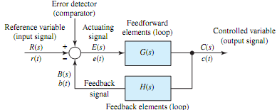
Referring to Figure, assuming the input and output signals are of the same dimension and are at the same level before subtraction, with a nonunity element H(s) incorporated in the feedback path, the error of the feedback control system is defined as

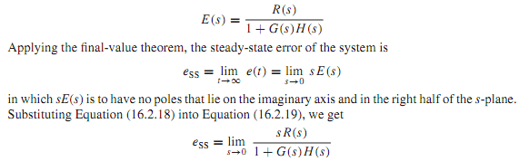
e(t) = r(t) - b(t) or E(s) = R(s) - B(s) = R(s) - H(s)C(s) or using Equation,
692_Transient behavior of a control system1.png

which apparently depends on the reference input R(s) and the loop gain (loop transfer function) G(s)H(s).

The type of feedback control system is decided by the order of the pole of G(s)H(s)at s = 0. Thus, if the loop gain is expressed as

721_Transient behavior of a control system2.png

where K and all of the T are constants, the exponent of s, i.e., q, in the denominator represents the number of integrations in the open loop, and the exponent q defines the system type. With q = 0, 1, or 2, the system is classified as position, velocity, or acceleration system, respectively.


Related Discussions:- Explain steady-state error of linear systems

Spectrum analyser, The spectrum analyser plots amplitude against frequency,...

The spectrum analyser plots amplitude against frequency, in other words it shows signals in the frequency domain. The spectrum analyser has the same trigger options as the oscillos

Explain working of resistance-capacitance coupled amplifiers, Q. Explain wo...

Q. Explain working of Resistance-capacitance coupled Amplifiers? Resistance-capacitance (RC)-coupled  Amplifiers : The following figure illustrates the most widely used method

What is choke packet, a. Explain Choke packet. Describe implicit Congestion...

a. Explain Choke packet. Describe implicit Congestion Signalling and explicit Congestion Signalling in Congestion control. b. State routing parameters in packet switching networ

Merits and demerits of fixed bias, Merits: 1.      It is very simple to...

Merits: 1.      It is very simple to shift the operating point anywhere in the active region by just changing the base resistor (R B ). 2.      A very small number of compon

Types of field-effect transistors, Types of Field-Effect Transistors T...

Types of Field-Effect Transistors The channel of a FET (field-effect transistor) is doped to produce either an N-type semiconductor or a P-type semiconductor. The drain and so

Dual-ramp analog to digital converter, Q. Dual-ramp analog to digital conve...

Q. Dual-ramp analog to digital converter? Figure (a) shows the block diagram of a dual-ramp (dual-slope) A/D converter. After a start-of-conversion pulse, the counter is cleare

How do you modify the direction of rotation of a d.c. motor, Q. How do you ...

Q. How do you modify the direction of rotation of a D.C. motor? Ans: The direction of rotation of DC motor will be changed either by changing the field winding connections o

Details of a distribution transformer, Electrical network details: 1  ...

Electrical network details: 1          single line diagrams with conductor sizes, transformer locations, consumer location, lengths, capacitors, and load, etc., 2

Write Your Message!

Captcha
Free Assignment Quote

Assured A++ Grade

Get guaranteed satisfaction & time on delivery in every assignment order you paid with us! We ensure premium quality solution document along with free turntin report!

All rights reserved! Copyrights ©2019-2020 ExpertsMind IT Educational Pvt Ltd