Explain cascading of multiple pics 8259, Electrical Engineering

Assignment Help:

Explain cascading of multiple PICS 8259. 

The 8259A adds 8 vectored priority encoded interrupts to the microprocessor. It can be expanded to 64 interrupt requests by using one master 8259A and 8 slave units. CS and WR must be decoded. Other connections are direct to microprocessor.  The pins D7 - D0: the bidirectional data connection, IR7 - IR0: Interrupt request, used to request an interrupt & connect to a slave in a system with multiple 8259A.

WR: Attaches to a write strobe signal (lower or upper into a 16 bit system) ,

RD: Attaches to the IORC signal, 

INT:  Attaches to the INTR pin on the microprocessor from the master and is Attached to a IR pin onto a slave and 

INTA: Attaches to the INTA pin onto the microprocessor.

Within a system only the master INTA signal is attached

A0:- Selects various command words with in the 8259A, 

CS: Chip select - It enables the 8259A for control and programming, 

SP/EN: Slave Program (1 for master, 0 for slave)/Enable Buffer (controls the data bus transceivers in a huge microprocessor based system while in buffered mode) and 

CAS2-CAS0: Used as outputs by the master to the slaves into cascaded systems. 

 548_cascading multiple 8259.png

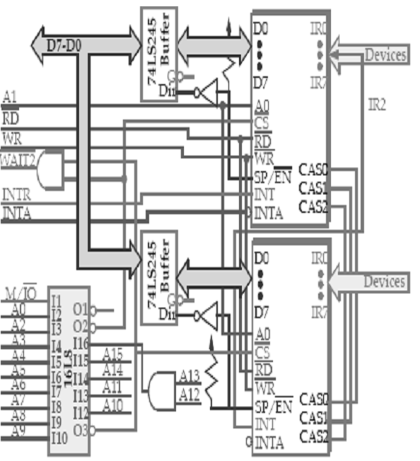
Fig: cascading multiple 8259


Related Discussions:- Explain cascading of multiple pics 8259

MATLAB, Future scope on MATLAB in India

Future scope on MATLAB in India

Derive lames equation for a thick cylinder, Derive Lame's equation for a th...

Derive Lame's equation for a thick cylinder subjected to internal pressure with clean diagrams. Evaluate the maximum and minimum hoop stresses across the section of a pipe of400

Explain basic principle of linear sweep voltage generator, Q. Explain the b...

Q. Explain the basic principle of linear sweep voltage generator A linear time base generator or sweep generator is one that provides an output waveform, a portion of which exh

Determine the thevenin resistance, Q. Determine the Thevenin resistance vie...

Q. Determine the Thevenin resistance viewed from terminals A-B of the circuit of Figure by setting independent sources to be zero and applying a test voltage at terminals A-B.

Crt and cro, working principle of crtand block diagram of cro

working principle of crtand block diagram of cro

Cipper, when i/p voltg is grater than battery diode is clse or open

when i/p voltg is grater than battery diode is clse or open

Explain working of digital-to-analog converters, Q. Explain working of Digi...

Q. Explain working of Digital-to-Analog Converters? Digital-to-Analog (D/A) Converters For the results of digital computations to be used in the analog world, it becomes n

Evaluate reference voltage, Q. Consider the 4-bit R-2R ladder D/A converter...

Q. Consider the 4-bit R-2R ladder D/A converter with V ref =-10 V. Determine the analog output voltage when the binary input code is 1100. Also, find what reference voltage is to

What are program-invisible registers, What are program-invisible registers?...

What are program-invisible registers? The local and global descriptor tables are determined into the memory system. So as to access and give the address of these tables, the pr

Write Your Message!

Captcha
Free Assignment Quote

Assured A++ Grade

Get guaranteed satisfaction & time on delivery in every assignment order you paid with us! We ensure premium quality solution document along with free turntin report!

All rights reserved! Copyrights ©2019-2020 ExpertsMind IT Educational Pvt Ltd