Equivalent circuit of a dc machine, Electrical Engineering

Assignment Help:

Equivalent Circuit of a DC Machine

A review of the material presented with regard to elementary direct-current machines can be helpful at this stage to recall the principles of operation for dc machines. The circuit representations of a dc generator and a dc motor are shown in Figure. Under steady-state conditions the interrelationships between voltage and current are given by

519_Equivalent Circuit of a DC Machine1.png

36_Equivalent Circuit of a DC Machine.png

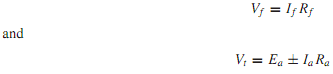
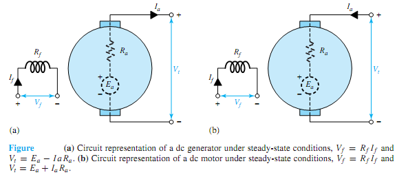
where the plus sign signifies a motor and the minus sign a generator. Vf is the voltage applied to the field circuit, If is the field current, and Rf is the field-winding resistance. Vt is the terminal voltage, Ea is the generated emf, Ia is the armature current, and Ra is the armature resistance. The generated emf Ea is given by Equation as

Ea = Kaφωm

which is the speed (motional) voltage induced in the armature circuit due to the flux of the stator-field current. The electromagnetic torque Te is given by Equation as

Te = KaφIa

where Ka is the design constant. The product EaIa, known as the electromagnetic power being converted, is related to the electromagnetic torque by the relation

Pem = EaIa = Teωm

For amotor, the terminal voltage is always greater than the generated emf, and the electromagnetic torque produces rotation against a load. For a generator, the terminal voltage is less than the generated emf, and the electromagnetic torque opposes that applied to the shaft by the prime mover.


Related Discussions:- Equivalent circuit of a dc machine

power system operation, AskWrite short notes on pit head generation. ques...

AskWrite short notes on pit head generation. question #Minimum 100 words accepted#

Calculate maximum reactive power the generator can produce, A 3-phase, wye-...

A 3-phase, wye-connected, 11.8 kV, 100 MVA turbo- generator of 0.8 power factor lagging has a synchronous reactance of 2.0 p.u. on rating. The generator is driven by a steam turbin

Mobile communications, Problem: (a) Compare the different MAC schemes...

Problem: (a) Compare the different MAC schemes, namely FDMA, SDMA, TDMA and CDMA. (b) Describe with help of diagrams the different phenomena involved in multipath propaga

Convert number systems from one base to another, Convert number systems fro...

Convert number systems from one base to another, and apply the binary number system to logic circuits 1.   Convert the following decimal numbers to binary a.   81 10 b.

calculate the current, Find the Thévenin equivalent for the attache...

Find the Thévenin equivalent for the attached circuit and use this to calculate the current in the load.   Circuit information:- Load consists

Input output, Input output The parallelogram symbol  is used to repres...

Input output The parallelogram symbol  is used to represent the input output  process as shown  below.                 IN01H

What are the hardware elements in the embedded systems, What are the hardwa...

What are the hardware elements in the embedded systems? Hardware Elements in the Embedded Systems are as follows: (i) Power Source (ii) Clock Oscillator Circuit and Clock

Explain power-system loads, Q. Explain Power-System Loads? Figure repre...

Q. Explain Power-System Loads? Figure represents a one-line (single-line) diagram of a part of a typical three-phase power system. Notice the symbols that are used for generato

What is the desirable properties of an insulation material, What is the des...

What is the desirable properties of an insulation material? Insulation materials have the desirable properties are as follows: 1. Very fine dielectric strength such as of mi

Write Your Message!

Captcha
Free Assignment Quote

Assured A++ Grade

Get guaranteed satisfaction & time on delivery in every assignment order you paid with us! We ensure premium quality solution document along with free turntin report!

All rights reserved! Copyrights ©2019-2020 ExpertsMind IT Educational Pvt Ltd