Discuss about signal distortion in optical waveguides
Ans: The major reason for signal distortion within optical waveguide is dispersion. Dispersion of the transmitted optical signal causes distortion for both digital analog transmissions along the optical fibers. While considering the main implementation of the optical fiber transmission that includes some form of digital modulation, the dispersion mechanism inside the fiber causes broadening of the transmitted light pulses as they travel along the channel. The major purpose for the broadening of the signal pulse is inter-symbol interference (ISI).
Dispersion is classified into
1. Intermodal
2. Intramodal (chromatic)
- Material dispersion
- Waveguide dispersion
The reason for the inter modal dispersion is the number of modes inside the fiber. As the number modes passes by the fiber, the various modes travel different distances, so in which they reach at the destination at various times. The pulse at the output is depends upon the transmission times of the slowest and fastest modes. For a single mode fiber the intermodal dispersion is absent and for the step index multimode fiber inter modal dispersion effect is extremely high. To overcome this we use multimode graded index fibers.
Intra modal dispersion or chromatic dispersion might occur in all kinds of optical fibers and results from the finite spectral width of optical source, because optical sources does not emit only a single frequency, but a band of frequencies, then there might be propagation delay differences among the different spectral element of the transmitted signal. This causes broadening of every transmitted mode and therefore intra modal dispersion. The delay differences might be caused through dispersive properties of the material (material dispersion) and also guidance effects inside the fiber structure (waveguide dispersion).
Pulse broadening because of material dispersion results from the different group velocities of several spectral elements launched into the fiber from the optical source. It occurs when the phase velocity of plane wave propagating in the dielectric medium varies non-linearly along with wavelength, and a material is said to exhibit material dispersion while the second order differential of the refractive index along with respect to wavelength is not zero,
Ie, d2n/dλ2 ≠ 0
The variation of material dispersion along with wavelength is display below:
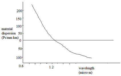
It might be observed that, the material dispersion tends to zero in the longer wavelength region around 1.3 µm for pure silica as display above. It can also be decreased through injection laser along with a narrow spectral width rather than an LED as the optical source.
The wave guiding of the fiber might also cause intra modal dispersion. This results from the variations in group velocity along with wavelength for a particular mode. Considering the ray theory approach it equivalent to the angle among the ray and the fiber axis varying along with wavelength that subsequently leads to variations in the transmission times for the rays, and hence dispersion. For a single mode fiber, whose propagation constant β, the fiber exhibit waveguide dispersion when,
d2β/dλ2 ≠0
Therefore these type of dispersion cause signal distortion.