Determine reactions on compound beams , Mechanical Engineering

Assignment Help:

Determine reactions on compound beams:

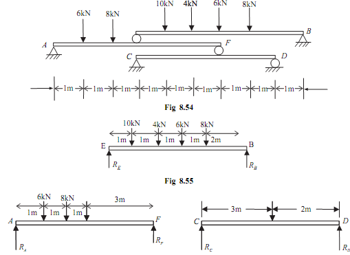
Determine reactions at the support A, B, C, and D for arrangement of compound beams shown in the figure given below.
 

611_Determine reactions on compound beams.png

Sol.: This is the question of multiple beams (that is, beam on a beam). In this type of question, consider the top most beam, then 2nd last beam as, In this problem on E and F, there are roller support, and this give reaction to both up and down beam. Consider free body digram of top most beams EB as shown in the given figure.

V = 0;

RE  + RB  - 10 - 4 - 6 - 8 = 0

RE  + RB = 28KN                                                                                                   ...(i)

Now taking moment about 'E'

10 × 1 + 4 × 2 + 6 × 3 + 8 × 4 - RB  × 6  = 0

RB = 11.33 KN                                   .......ANS

Putting the value of RB  in the equation (i)

RE = 16.67 KN                                   .......ANS

Consider free body digram of second beam AF as shown in fig 8.56:

∑V = 0;

RA  + RF  - 6 - 8 - RE = 0

RA  + RF = 30.67 KN                                                                                          ...(ii)

Now taking moment about 'A'

6 × 1 + 8 × 2 + 16.67 × 3 - RF × 6  = 0

RF = 12 KN                                        .......ANS

Putting the value of RF  in the equation (ii)

RA = 18.67 KN                                   .......ANS

Consider FBD of third beam CD as shown in the given figure:

∑V = 0;

RC  + RD  - RF = 0

RC  + RD = 12 KN                                                                                               ...(iii)

Now taking moment about 'C'

- RD  × 5 + 12 × 3 = 0

RD = 7.2 KN                                       .......ANS

Putting value of RD  in the equation (iii)

RC = 4.8 KN                                        .......ANS


Related Discussions:- Determine reactions on compound beams

Maximum stress in the beam due to bending, For the beam shown below, we nee...

For the beam shown below, we need to determine: (i)  the support reactions R L and R R (ii) the shear force and bending moment diagrams (iii) the maximum stress in the b

Dynamics, A rectangular plate has two holes of dimensions shown and is rele...

A rectangular plate has two holes of dimensions shown and is released from the position shown. The plate is hinged about a horizontal axis and can rotate in the vertical plane. An

Find out the moment of inertia of an annular area, Find out the moment of i...

Find out the moment of inertia of an annular area: Find out the M. I. of an annular area among two circles where difference of radius is quite small, around any centroidal axi

What is pedestal and what are uses of pedestal, What is pedestal? What are ...

What is pedestal? What are uses of pedestal? PEDESTALS A pedestal is used to transfer the loads from the metal columns through the floor and soil to the footing when it is a

Clutch free play-gear complaints, Clutch free play: Check for free play of...

Clutch free play: Check for free play of the clutch lever, it should be within 10-20 mm.

Design a shaft to transmit power, Design a shaft to transmit power from a m...

Design a shaft to transmit power from a motor to a lathe head stock through a pulley by means of a belt drive. The pulley weighs 200 N and is located at 300 mm from the centre of t

Resulting structure of steel, Resulting structure of steel: Heat treat...

Resulting structure of steel: Heat treatments as mentioned below are given to thin steel strips for which TTT diagram is as shown in Figure 19. What will be the resulting stru

Motion of two bodies - rough surface and smooth pulley, Motion of two bodie...

Motion of two bodies - rough surface and smooth pulley: THE HORIZONTAL SURFACE IS ROUGH AND THE STRING IS PASSING OVER SMOOTH PULLEY. Figure shows two weights W 1 and W 2

MOS, limitations of euler''s theory

limitations of euler''s theory

Relation between stress and strain, Relation between stress and strain: ...

Relation between stress and strain: The relation between stress and strain is generally shown by plotting a stress-strain (σ -e) diagram. Stress can be plotted on ordinate (ve

Write Your Message!

Captcha
Free Assignment Quote

Assured A++ Grade

Get guaranteed satisfaction & time on delivery in every assignment order you paid with us! We ensure premium quality solution document along with free turntin report!

All rights reserved! Copyrights ©2019-2020 ExpertsMind IT Educational Pvt Ltd